Power take-off system and gearbox integrated with oil pump

A gearbox and oil pump technology, which is applied in the direction of pressure lubrication of lubricating pumps, pressure lubricants, and engine lubrication, etc. It can solve the problems of reducing the volume of the casing, the length of the power take-off shaft, and the overall weight reduction, so as to ensure the lubrication efficiency , Ease of assembly and shortened length

Active Publication Date: 2022-06-28
DONGFENG COMML VEHICLE CO LTD
View PDF8 Cites 0 Cited by
  • Summary
  • Abstract
  • Description
  • Claims
  • Application Information

AI Technical Summary

Problems solved by technology

It has the advantages of simple structure, easy to use, and can meet the needs of fire-fighting vehicles. Its structure is as follows: it is mainly composed of the front case of the transmission, the middle case of the transmission and a one-axis power take-off installed between the two. For the transmission of the power take-off, the middle case of the transmission is connected to the connecting plate of the one-axis power take-off, the housing of the one-axis power take-off is also connected to the connecting plate, and the front case of the transmission is connected to the front end of the power take-off housing; the one-axis of the transmission , The left subshaft of the transmission, the front end of the right subshaft of the transmission are connected with the connecting plate of the power take-off; Oil pump; transmission middle case, power take-off connecting plate, power take-off housing and transmission front case are all equipped with interconnected oil passages to form a transmission forced lubrication system; it has the following defects: 1. The power take-off shaft is too long, which is inconvenient Processing, assembly, and transmission efficiency are limited; 2. An external lubrication system is required to lubricate the transmission part of the power take-off
The utility model has bolt holes with the same axis on the front shell of the power take-off and the rear shell of the power take-off. When installing, the whole power take-off can be directly installed on the transmission case without disassembly, which can reduce the power take-off. Failure rate; due to the overall installation of the power take-off, there is no need to separately reserve the installation hole of the front shell of the power take-off, which can reduce the volume of the shell, reduce the overall weight, and the production, processing and assembly cycle are faster. Through the spline on the output gear shaft The center hole is directly assembled with the oil pump shaft without output flange, which further reduces the cost, but it has the following defects: 1. The power take-off shaft is too long, which is not convenient for processing and assembly, and the transmission efficiency is limited; 2. An external lubrication system is required for the take-off The transmission part of the force device is used for moistening and mixing

Method used


Image

  • Power take-off system and gearbox integrated with oil pump
  • Power take-off system and gearbox integrated with oil pump
  • Power take-off system and gearbox integrated with oil pump

Examples


Embodiment 1

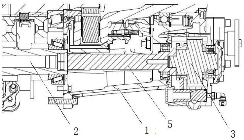
[0084]The invention discloses a power take-off system with an integrated oil pump. When a cooler and a filter are not installed on the rear casing, it includes a gearbox rear casing 100, and the rear casing 100 of the gearbox is integrated with a An oil inlet 25, an oil outlet 26 and a lubricating oil circuit for connecting the oil inlet 25 and the oil outlet 26, the lubricating oil circuit includes an oil inlet pipeline 108, an intermediate pipeline 109 and an oil outlet pipeline 116. The oil inlet pipeline 108 and the oil outlet pipeline 116 are blind holes arranged on the side wall of the rear casing, and the intermediate pipeline 109 is a blind hole arranged on the side wall of the rear casing. The hole structure, the multi-function transfer hole 120 and the oil passage hole 111 provided on the intermediate pipeline 109 may not be processed, and the intermediate pipeline 109 includes a coaxially arranged first pipe communicating with the oil outlet pipeline 116 A pipeline ...

Embodiment 2

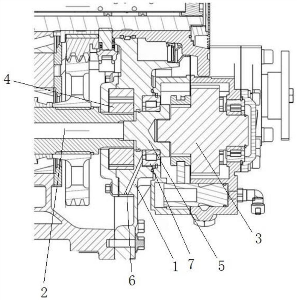
[0086] The invention discloses a power take-off system with an integrated oil pump. When only the filter 50 is installed on the rear casing, it includes a gearbox rear casing 100, and an oil inlet is integrated on the rear casing 100 of the gearbox. port 25, oil outlet 26 and a lubricating oil circuit for connecting the oil inlet 25 and the oil outlet 26, the lubricating oil circuit includes an oil inlet pipe 108, an intermediate pipe 109 and an oil outlet pipe 116, The oil inlet pipeline 108 and the oil outlet pipeline 116 are blind hole structures arranged on the side wall of the rear housing, and the intermediate pipeline 109 is a blind hole structure arranged on the side wall of the rear housing , the intermediate pipeline 109 is provided with a multi-function adapter hole 120 for connecting the filter installed on the rear housing with the oil outlet pipeline 116, and a multifunctional adapter hole 120 for connecting the filter installed on the rear housing with the oil ou...

Embodiment 3

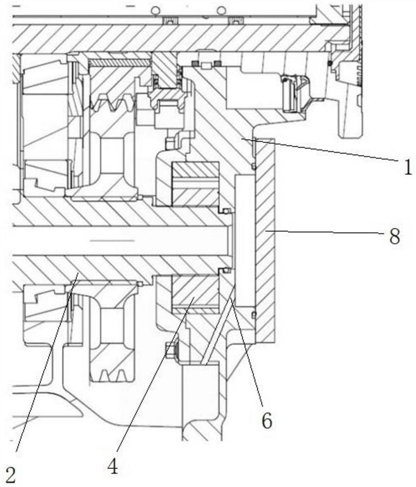
[0088]The present invention discloses a power take-off system with an integrated oil pump. When only a small cooler 60 is installed on the rear casing, it includes a gearbox rear casing 100, and an oil inlet is integrated on the rear casing 100 of the gearbox. port 25, oil outlet 26 and a lubricating oil circuit for connecting the oil inlet 25 and the oil outlet 26, the lubricating oil circuit includes an oil inlet pipe 108, an intermediate pipe 109 and an oil outlet pipe 116, The oil inlet pipeline 108 and the oil outlet pipeline 116 are blind hole structures arranged on the side wall of the rear housing, and the intermediate pipeline 109 is a blind hole structure arranged on the side wall of the rear housing , the intermediate pipeline 109 is provided with a multifunctional adapter hole 120 for connecting the small cooler installed on the rear casing and the oil outlet pipeline 116, and a small cooler installed on the rear casing and the oil outlet pipe 116. The oil passage ...


PUM


Abstract

The invention discloses a power take-off system of an integrated oil pump and a gearbox, which includes a casing, a power output shaft is arranged on the inside of the casing, a power take-off is arranged on the outside of the casing, and the power output shaft It is coaxially connected with the power take-off, and the housing is integrated with an oil pump rotor and a power take-off shaft arranged coaxially and rotatable around its own axis, and one end of the power take-off shaft is in transmission connection with the power output shaft , the other end of the power take-off shaft is in transmission connection with the power take-off, and the oil pump rotor is in transmission connection with the power output shaft. The invention can not only effectively shorten the length of the power take-off shaft, but also realize the self-lubrication of the power take-off.

Description

technical field [0001] The invention discloses a power take-off system and a gearbox, belonging to the technical field of gearboxes, and specifically discloses a power take-off system and a gearbox with an integrated oil pump. Background technique [0002] At present, the transmission of heavy commercial vehicles is mostly lubricated by active lubrication. The oil pump first pumps the lubricating oil to the filter device through the oil suction device for filtering, then cools the lubricating oil through the cooling device, and finally transports the lubricating oil through the oil passage or oil pipe. Go to each lubrication point of the gearbox for lubrication. During the lubrication process, a pressure limiting valve should be installed in the transmission oil circuit to protect the lubrication system from overpressure. Some gearboxes also spray lubricating oil on the meshing surfaces of the gearbox gears through the spray oil pipe. From the bottom of the gearbox casing ...

Claims


Application Information

Patent Timeline
Patent Type & Authority Patents(China)
IPC IPC(8): F01M1/02F01M1/10F01M1/20F01M11/00F01M11/03F02B63/06F02B67/04
CPCF01M1/02F01M1/10F01M11/03F01M1/20F01M11/00F02B63/06F02B67/04F01M2001/0253
Inventor 言梓谦张莉香李剑平曹辞向盼张馨月郑万生
Owner DONGFENG COMML VEHICLE CO LTD
Why Eureka
Try Eureka