
An axial flow fan rotor blade adjustment device

A technology of adjusting device and axial flow air, which is applied in the direction of fluid pressure actuating device, machine/engine, mechanical equipment, etc. It can solve the problems of difficult processing, poor adjustment accuracy, and extremely high precision requirements, and achieve high processing quality and coordination Accuracy, reduced equipment cost, and simple installation process

Active Publication Date: 2021-11-09
中国电建集团透平科技有限公司
View PDF0 Cites 0 Cited by
  • Summary
  • Abstract
  • Description
  • Claims
  • Application Information

AI Technical Summary

Problems solved by technology

However, due to the poor adjustment accuracy, low reliability and internal leakage of this structure, it is gradually replaced by an electro-hydraulic control system based on a proportional valve, that is, the electromagnets at both ends of the proportional valve drive the movement of the proportional valve spool (that is, the spool valve) Rotary joint mechanism) to complete the position switching of the three-position four-way proportional valve, and finally realize the forward and backward movement of the hydraulic cylinder piston
[0004] But this kind of slide valve rotary joint has the following problems: First, the design requires extremely high radial and axial dimensional accuracy for the cooperation between the valve sleeve and the valve core, and the processing is difficult; second, the valve sleeve and the valve core need to be It can move relative to the axial direction, and is easily affected by oil quality, resulting in abrasive wear, which leads to the failure of the gap seal; third, the structure cannot prevent the reverse flow of oil in the oil circuit, so it does not have the design basis for the function of retaining the rotor blade, which is manifested as Once the hydraulic oil is cut off, the installation angle of the blade will change randomly under the action of the load moment and internal leakage of the working condition

Method used


Image

  • An axial flow fan rotor blade adjustment device
  • An axial flow fan rotor blade adjustment device
  • An axial flow fan rotor blade adjustment device

Examples


Embodiment Construction

[0037] In order to make the purpose, technical solutions and advantages of the embodiments of the present invention clearer, the technical solutions in the embodiments of the present invention will be clearly and completely described below in conjunction with the accompanying drawings in the embodiments of the present invention. Obviously, the described embodiments It is some embodiments of the present invention, but not all of them. Based on the implementation manners in the present invention, all other implementation manners obtained by persons of ordinary skill in the art without creative efforts fall within the protection scope of the present invention.

[0038] Accordingly, the following detailed description of the embodiments of the invention provided in the accompanying drawings is not intended to limit the scope of the claimed invention, but merely represents selected embodiments of the invention. Based on the implementation manners in the present invention, all other ...


PUM


Abstract

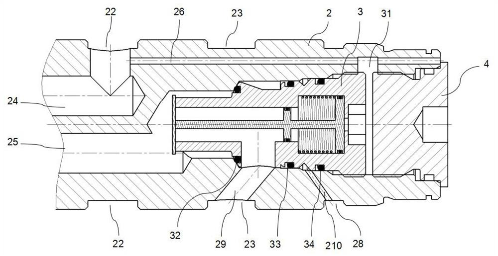
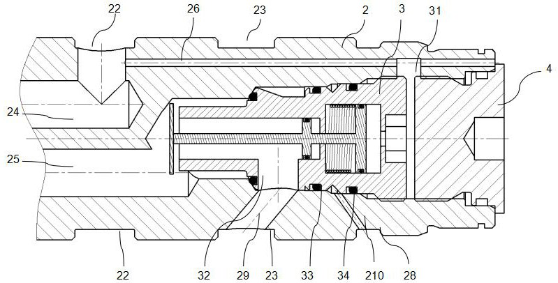
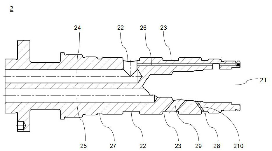
The invention is applicable to an axial flow fan, and provides an adjusting device for the moving blades of the axial flow fan. The device includes a valve casing assembly, a mandrel, a hydraulically controlled switch assembly, and a first seal; the control end of the mandrel is sealed and accommodated in the first accommodating cavity of the valve casing assembly, and the mandrel is in clearance fit with the valve casing assembly; The control switch assembly is accommodated in the second accommodating cavity on the mandrel, and a closed control oil chamber is formed between the hydraulic control switch assembly and the first sealing assembly; the first annular pressure on the mandrel The oil groove and the second annular pressure oil groove communicate with the first oil passage and the second oil passage respectively, and the hydraulic control switch assembly is used to open or close the communication channel between the second oil passage and the second annular pressure oil groove. The invention of the gap seal can achieve almost no internal leakage; its processing difficulty is low, and its assembly accuracy is high; it is not sensitive to oil quality and abrasive wear when used with a proportional valve; when the hydraulic oil is interrupted, it can instantly realize the function of maintaining the position of the blade.

Description

technical field [0001] The invention relates to an axial flow fan, in particular to an axial flow fan blade adjustment device. Background technique [0002] Axial fans with adjustable rotor blades can adjust the installation angle of the rotor blades to match different system working conditions, and at the same time make the adjusted fans work in the high-efficiency area, so they are widely used in thermal power, metallurgy, mines, tunnels and other industries. in the smoke system. However, in the prior art, the rotor blade adjustment system of the axial flow fan with adjustable rotor blades makes the structure of the fan complex, and its manufacturing precision and reliability are extremely high. [0003] In the prior art, for the adjustment of the movable blades of the axial flow fan with adjustable movable blades, a mechanical adjustment mechanism is mainly used, that is, a sliding valve type rotary joint is dragged by a mechanical structure. However, due to the poor ad...

Claims


Application Information

Patent Timeline
Patent Type & Authority Patents(China)
IPC IPC(8): F15B15/14F15B15/20F15B13/02F04D27/00
CPCF15B15/1423F15B15/1428F15B15/1461F15B15/1476F15B15/149F15B15/202F15B13/021F04D27/002
Inventor 曾庆龙邱凌刘强邹文辉代彦铭李涛
Owner 中国电建集团透平科技有限公司
Learn More