Perforated yield type energy dissipator
A technology of energy dissipators and connecting holes, applied in the direction of shock absorbers, shock absorbers, springs/shock absorbers, etc., can solve the problems of inconvenient installation and replacement, complex structure, etc., to achieve convenient disassembly and maintenance, energy consumption The mechanism is clear and the effect of improving energy consumption capacity
- Summary
- Abstract
- Description
- Claims
- Application Information
AI Technical Summary
Problems solved by technology
Method used
Image

Examples
Embodiment 1
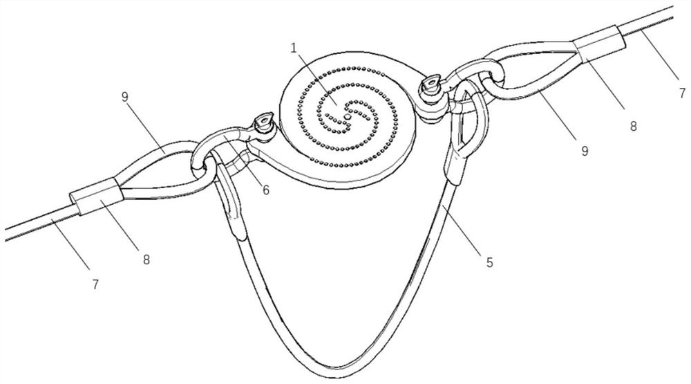
[0063] Such as figure 2 As shown, a design method of perforated yield energy dissipator. When used alone, the energy dissipator includes a metal disc 1 with holes, a protection rope 5 and two shackles 6 .
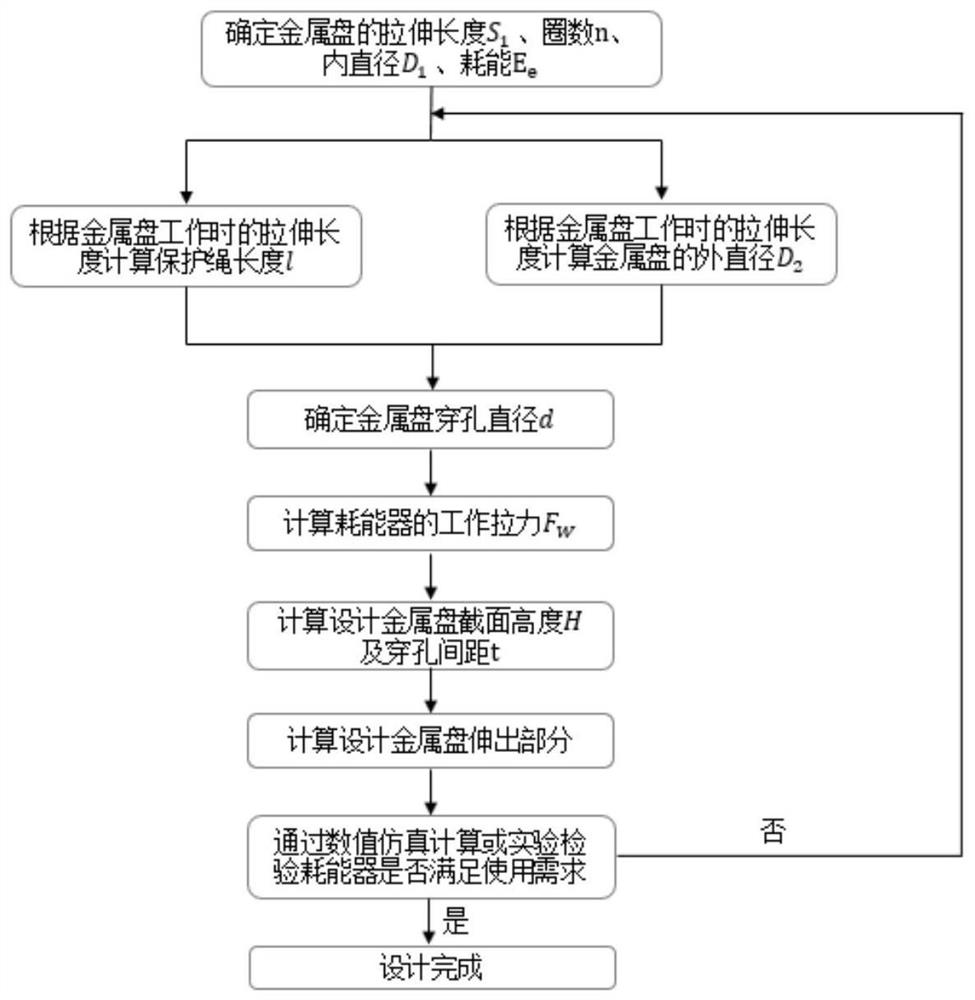
[0064] according to figure 1 Computational design is performed as shown in the design flow:
[0065] Determine the tensile length, number of helical turns, and inner diameter of the metal disc when it is working: according to the allowable slip length and space of the steel wire rope in the flexible protection system connected in this embodiment, the tensile length S of the energy dissipator in this embodiment 1 is 1500mm, the number of spiral turns n of the single arm of the metal disc is 1.5, and the inner diameter D 1 80mm;
[0066] Calculate the length of the protection rope according to the stretching length of the metal disc when it is working: according to the formula l=1.1S 1 Calculate the length of the protection rope, the stretching length of the metal disc ...
Embodiment 2
[0079] Such as Figure 7 , Figure 8 As shown, a design method of perforated yield energy dissipator. When the energy waster is used in parallel combination according to this embodiment, it includes 4 metal discs 1 with holes and 1 connecting bolt 10 .
[0080] Such as Figure 9 As shown, when the energy dissipator is used in parallel combination according to this embodiment, according to the method in embodiment 1, four metal discs 1 with holes are connected in parallel through bolts 10 to form the energy dissipator when used in parallel combination according to this embodiment. main structure.
[0081] The main structure ( Figure 9 ) through the connection structure ( Figure 4 ) is connected with the steel wire rope of the flexible protection system to form Figure 7 , Figure 8 Shown is the complete structure of the energy consumer when used in combination according to this embodiment.
[0082] When the flexible protection system is impacted, the steel wire rope i...
Embodiment 3
[0084] Such as Figure 10 As shown, a design method of perforated yield energy dissipator. The energy dissipator comprises two metal discs 1 with holes and one "8"-shaped steel cable 11 when used in series according to this embodiment.
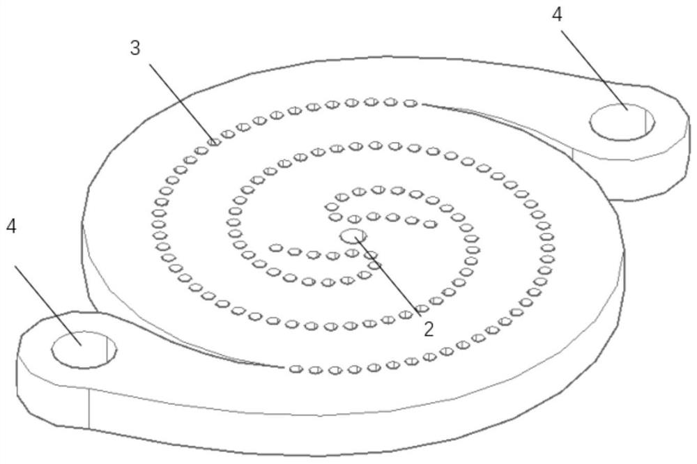
[0085] The main structure ( image 3 ) is connected by an "8"-shaped steel cable, and then connected with the flexible protection system steel wire rope, thus forming Figure 10 Shown is the complete structure of the energy consumer when used in series and combined according to this embodiment.
[0086] According to this embodiment, when the energy consumers are combined in series, the maximum slippage of the steel wire rope of the flexible protection system can be increased by 2 times.
PUM
 Abstract
Description
Claims
Application Information
 - R&D
- Intellectual Property
- Life Sciences
- Materials
- Tech Scout
- Unparalleled Data Quality
- Higher Quality Content
- 60% Fewer Hallucinations
Browse by: Latest US Patents, China's latest patents, Technical Efficacy Thesaurus, Application Domain, Technology Topic, Popular Technical Reports.
© 2025 PatSnap. All rights reserved.Legal|Privacy policy|Modern Slavery Act Transparency Statement|Sitemap|About US| Contact US: help@patsnap.com