Optical fiber displacement sensing method based on Raman backscattering

A backscattering, optical fiber technology, applied in the direction of using optical devices, measuring devices, instruments, etc., can solve the problems of increased probability of system failure, complex system, and increased application cost.

Active Publication Date: 2021-09-03
ANHUI NORMAL UNIV
View PDF6 Cites 0 Cited by
  • Summary
  • Abstract
  • Description
  • Claims
  • Application Information

AI Technical Summary

Problems solved by technology

If multiple sensing systems are used to measure multiple parameters, the application cost will inevitably in

Method used


Image

  • Optical fiber displacement sensing method based on Raman backscattering
  • Optical fiber displacement sensing method based on Raman backscattering
  • Optical fiber displacement sensing method based on Raman backscattering

Examples


Example Embodiment

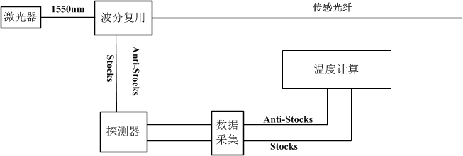
[0019] On the basis of the existing Raman distributed optical fiber temperature sensing system, the present invention utilizes Stocks Backscattered light realizes a kind of optical fiber displacement sensing system and sensing method, the structure of optical fiber displacement sensing system is as follows figure 2 shown.

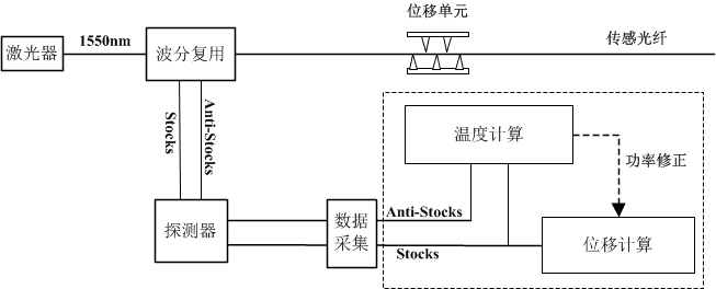
[0020] The displacement calculation algorithm flow is as follows: image 3 As shown, the specific calculation method is as follows.

[0021] Step 1: Acquisition card continuous acquisition 40960 strip Stocks and Anti-stocks Backscattering curves, and then respectively for Stocks and Anti-stocks The backscattering curves were accumulated and averaged ( y=(x 1 +x 2 +……x k ) / k, k=40960 ). Then for the accumulated Stocks and Anti-stocks The backscattering curves were averaged by moving average ( , M is the step size of the moving average, y i is the first on the curve i data points), the step size of the moving average M=7 .

...


PUM


Abstract

The invention discloses an optical fiber displacement sensing system and a sensing method based on a Raman backscattering principle. The method in the specific technical scheme comprises the following steps that 1) an acquisition card converts an analog signal output by a detector into a digital signal, and then performs accumulative average and transverse moving average processing on a Raman backscattering curve to reduce a noise signal; 2) a temperature value iscalculated by using the Stockes and Anti-stockes backscattering signals, and power correction is conducted on the Stockes backscattering signals by using the calculated temperature data; 3) a loss value of the Stockes backscattering signal is calculated, and a displacement loss value of a plurality of Stockes signals at the same position is extracted; (4) loss data of the same position of the plurality of Stockes signals are drawn into a curve, and nonlinear fitting is conducted on the curve to obtain fitting parameters of the curve; and (5) fitting is conducted on the acquired displacement loss data by utilizing the curve fitting parameters, and calculation is conducted to obtain a displacement value of the optical fiber.

Description

technical field [0001] The invention relates to a distributed optical fiber displacement sensing method, in particular to a signal processing method of an optical fiber displacement sensing system based on Raman backscattering. Background technique [0002] Due to its simple structure, long detection distance, and immunity to electromagnetic interference, distributed optical fiber sensors have become research hotspots at home and abroad in recent years. Distributed optical fiber sensing system is mainly used in transportation, construction, electric power, coal mine, petrochemical and other industries, and its role is to measure various parameters of these important places in real time. It plays an important role in ensuring the normal operation of industrial system equipment and ensuring the safety of life and property. At present, distributed optical fiber sensing technologies mainly include: distributed optical fiber temperature sensing technology, distributed optical fi...

Claims


Application Information

Patent Timeline
IPC IPC(8): G01B11/02
CPCG01B11/02
Inventor 周正仙郑贤锋张大伟崔执凤屈军韩亚帅杨新艳余瑞兰冯小蔚朱晶晶徐晓峰陶天宝
Owner ANHUI NORMAL UNIV
Why Eureka
Try Eureka