Optical fiber temperature and humidity sensor

A humidity sensor, optical fiber temperature technology, applied in the direction of instruments, measuring instrument components, locking devices when the movable parts of the measuring device are not in use, etc., can solve the problem that it is difficult for the operator to grasp the angle of rotation, affect the accuracy of the detection data, Increase the difficulty of device adjustment and other issues to achieve the effects of improving stability, ensuring accuracy, and improving accuracy

Inactive Publication Date: 2021-09-03
宫晓钰
View PDF1 Cites 1 Cited by
  • Summary
  • Abstract
  • Description
  • Claims
  • Application Information

AI Technical Summary

Problems solved by technology

[0004] The above invention fixes the detection platform through the lock nut through the fixed part. Therefore, if it is necessary to detect other parts of the component to be detected during the detection process, the lock nut needs to be disassembled and then the angle of the adjustment device is used. The lock nut is used to fix it. This method is not only very cumbersome to operate, but also makes it difficult for the operator to grasp the angle of rotation, especially when testing components in a semi-enclosed narrow testing space, it is difficult for the operator to pass through the eyes. The rotation angle of the sensor is observed, thus increasing the difficulty of adjusting the device and affecting the accuracy of the detection data

Method used


Image

  • Optical fiber temperature and humidity sensor
  • Optical fiber temperature and humidity sensor
  • Optical fiber temperature and humidity sensor

Examples


Embodiment Construction

[0034] The following will clearly and completely describe the technical solutions in the embodiments of the present invention with reference to the accompanying drawings in the embodiments of the present invention. Obviously, the described embodiments are only some, not all, embodiments of the present invention. Based on the embodiments of the present invention, all other embodiments obtained by persons of ordinary skill in the art without making creative efforts belong to the protection scope of the present invention.

[0035] see Figure 1 to Figure 9 , the present invention provides a technical solution:

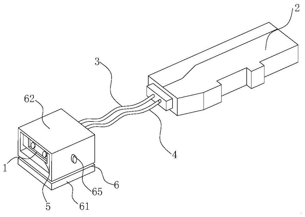
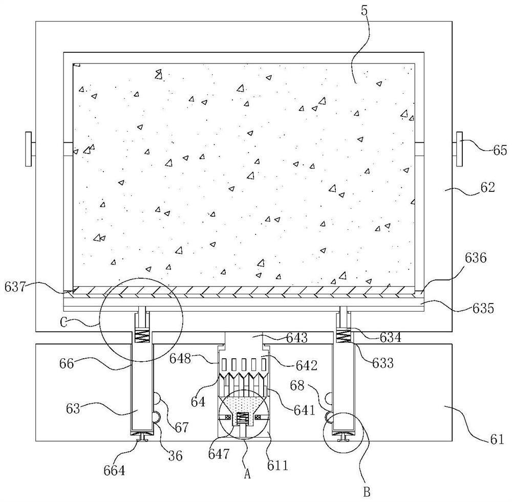
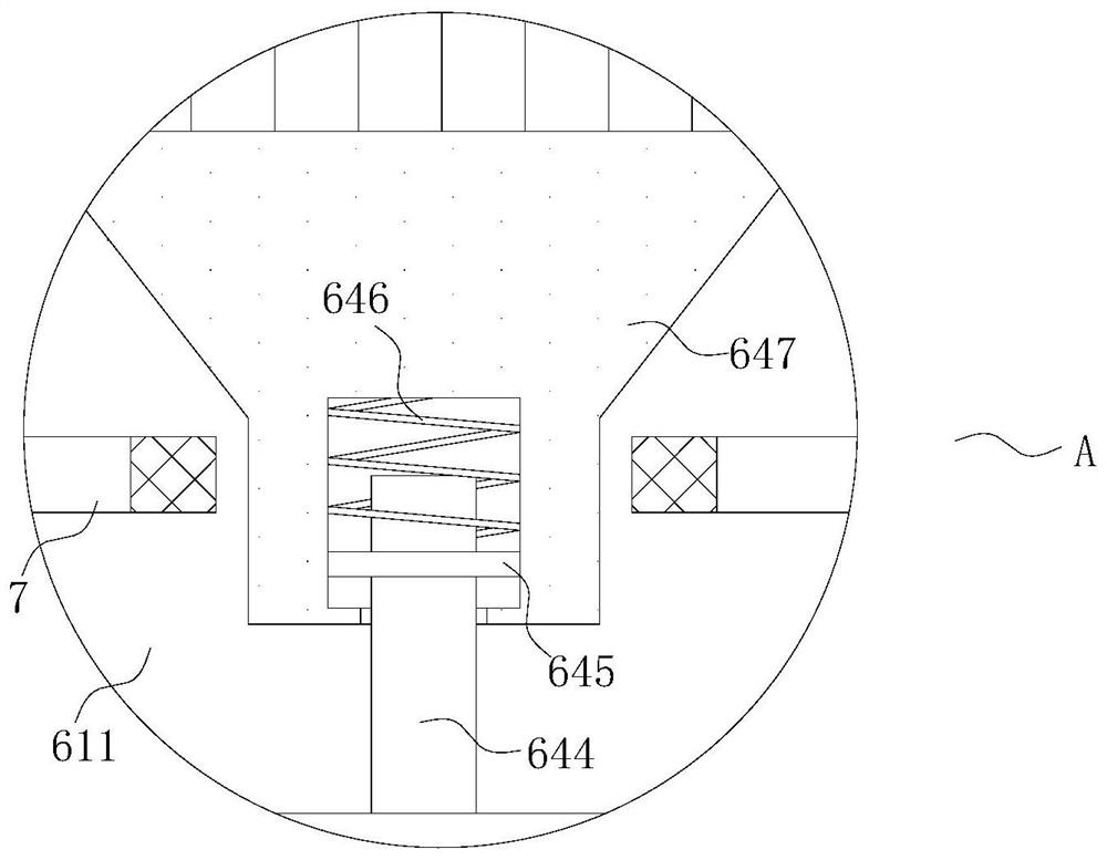
[0036] An optical fiber temperature and humidity sensor, such as Figure 1 to Figure 9 As shown, it includes a detection head 1, an amplifier 2, an optical fiber cord 3, a power cord 4, a housing 5 and a fixing mechanism 6, and the detection head 1 and the amplifier 2 are electrically connected to the power cord 4 through an optical fiber cord 3, and The outer surface o...


PUM


Abstract

The invention relates to the technical field of optical fiber sensors, in particular to an optical fiber temperature and humidity sensor which comprises a detection head, an amplifier, an optical fiber cable, a power line, a shell and a fixing mechanism, the detection head and the amplifier are electrically connected through the optical fiber cable and the power line, the shell is arranged on the outer surface of the detection head, and the fixing mechanism is connected with the shell. The fixing mechanism comprises a base, a connecting shell, a rotating ring and an automatic telescopic locking assembly, the connecting shell is arranged outside the shell and movably connected with the shell, and threaded holes are formed in the outer surfaces of the two sides of the connecting shell. According to the invention, through the arrangement of the fixing mechanism and the clamping mechanism, the stability of the device can be ensured, the detection angle of the detection head can be conveniently adjusted by an operator, and the rotation angle of the detection head can be judged through the clamping condition of the clamping mechanism and the first arc-shaped groove, so that the accuracy of detection data of the device is improved; and the operation mode is convenient, and the application range of the device is effectively expanded.

Description

technical field [0001] The invention relates to the technical field of optical fiber sensors, in particular to an optical fiber temperature and humidity sensor. Background technique [0002] With the rapid development of fiber optic sensing technology, fiber optic sensors have been widely used in various monitoring as the preferred monitoring element in structural monitoring. [0003] Existing patent (notification number: CN211042264U) a fiber optic sensor, including a detection head and an amplifier; the amplifier is connected with a power line and an optical fiber cable; the detection head includes a housing, and one end of the housing is provided with a detection port , the other end of the housing is provided with a first wiring port and a second wiring port, and the housing is provided with an accommodating cavity communicating with the detection port, the first wiring port and the second wiring port, A laser light source and an optical fiber detection head are provide...

Claims


Application Information

Patent Timeline
Patent Type & Authority Applications(China)
IPC IPC(8): G01D21/02G01D11/22G01D11/18
CPCG01D21/02G01D11/22G01D11/18
Inventor 宫晓钰孙辉东
Owner 宫晓钰
Why Eureka
Try Eureka