
Differential pressure transmitter verification system

A differential pressure transmitter, low pressure technology, applied in the field of differential pressure transmitter calibration system, can solve the problem of reducing the accuracy and resolution of calibration differential pressure

Active Publication Date: 2021-09-03
XINJIANG UYGUR AUTONOMOUS REGION INST OF MEASUREMENT & TESTING
View PDF10 Cites 1 Cited by
  • Summary
  • Abstract
  • Description
  • Claims
  • Application Information

AI Technical Summary

Problems solved by technology

The differential pressure calibration method of the dual-channel digital pressure instrument is mainly realized by the dual-channel pressure controller. However, the differential pressure calibration method of the dual-channel digital pressure instrument can only be used for the calibration of low static pressure differential pressure instruments. The biggest problem is It is a digital pressure instrument that will inevitably reduce the accuracy and resolution of the calibrated differential pressure while meeting the high static pressure

Method used


Image

  • Differential pressure transmitter verification system
  • Differential pressure transmitter verification system
  • Differential pressure transmitter verification system

Examples


Embodiment Construction

[0028] The present invention will be further described in detail below in conjunction with the accompanying drawings and embodiments.

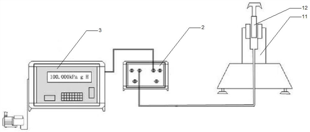
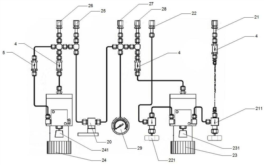
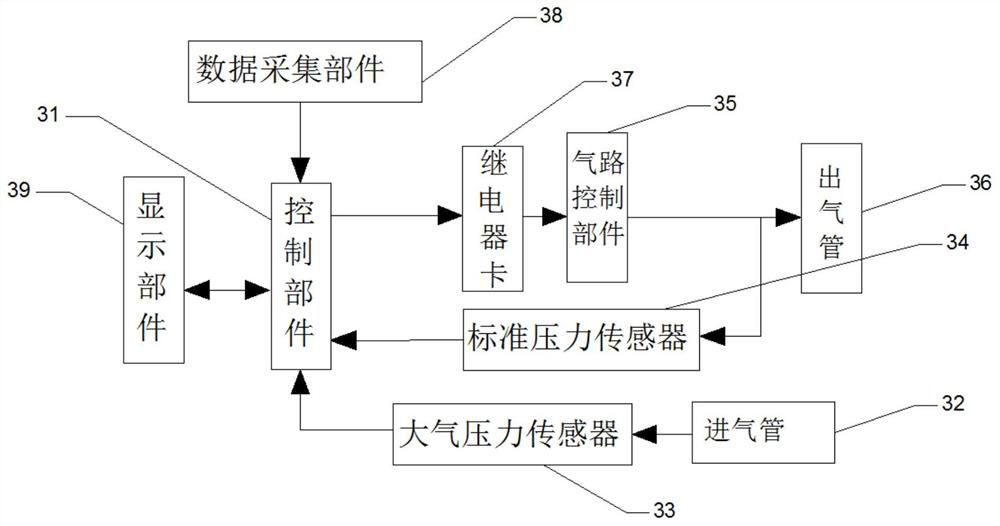
[0029] Such as Figure 1 to Figure 4 As shown, the embodiment of the present invention provides a differential pressure transmitter verification system, the system includes:

[0030] A pressure gauge component, the pressure gauge component includes a piston cylinder 11 and a piston body 12, and the piston body 12 is arranged on the piston cylinder 11;

[0031]Verification parts, the verification parts include air supply connecting pipe 21, exhaust connecting pipe 22, first regulator 23, second regulator 24, low pressure test pipe 25, low pressure reference pipe 26, high pressure test pipe 27, high pressure reference pipe 28 and Referring to the pressure gauge 29, one end of the gas supply connection pipe 21 is connected to the first regulator 23, one end of the high pressure test tube 27 is connected to the first regulator 23, and the other e...


PUM


Abstract

The invention discloses a differential pressure transmitter verification system, relates to the technical field of differential pressure transmitter verification equipment, and mainly aims to provide a differential pressure transmitter verification system capable of quickly, conveniently and accurately verifying and calibrating a differential pressure transmitter and a differential pressure flowmeter. According to the main technical scheme, the differential pressure transmitter verification system comprises a pressure gauge component, a verification component and a pressure supply component, a standard pressure value is provided for the high-pressure end of a differential pressure transmitter through the pressure gauge component, reference pressure is provided for the low-pressure end of the differential pressure transmitter through the pressure supply component, and the verification component is composed of two sets of verification instruments which are communicated with each other. A bypass valve is arranged between the two verification instruments, the two ends of the differential pressure transmitter can be connected or isolated through opening or closing of the bypass valve, the effect of generating a differential pressure value is achieved, and therefore verification and calibration work of the differential pressure type transmitter and the differential pressure type flowmeter can be achieved rapidly, conveniently and accurately. The differential pressure transmitter verification device is mainly used for calibrating the differential pressure transmitter.

Description

technical field [0001] The invention relates to the technical field of calibration equipment for differential pressure transmitters, in particular to a calibration system for differential pressure transmitters. Background technique [0002] The pressure transmitter is a kind of transmitter that is widely used at present. It is an instrument that converts the pressure variable into a transmittable standardized output signal, and there is a certain continuous linear relationship between the output signal and the pressure variable. The main For the measurement and control of pressure parameters in industrial processes. The differential pressure transmitter can be combined with other flow instruments to form a differential pressure flowmeter for flow integration. It is a livelihood measurement and energy measurement product related to trade settlement, and it is also the measurement instrument that is most prone to trade disputes. Therefore, the accuracy of differential pressur...

Claims


Application Information

Patent Timeline
Patent Type & Authority Applications(China)
IPC IPC(8): G01L27/00G01F25/00
CPCG01L27/00G01L27/005
Inventor 李海兵鲜青龙任建国卓华薛文艳仝立公袁恩阁赵亿坤
Owner XINJIANG UYGUR AUTONOMOUS REGION INST OF MEASUREMENT & TESTING
Learn More