
A fluxgate current sensor and current measurement method

A current sensor and fluxgate technology, which is applied in the direction of measuring current/voltage, measuring device, and only measuring current, can solve the problems of uneven distribution of magnetic induction intensity of magnetic materials, affecting the measurement accuracy of sensors, and low accuracy of current sensors , to achieve the effect of simple structure, reducing production error and improving measurement accuracy

Active Publication Date: 2022-08-09
HEFEI ECRIEE TAMURA ELECTRIC
View PDF18 Cites 0 Cited by
  • Summary
  • Abstract
  • Description
  • Claims
  • Application Information

AI Technical Summary

Problems solved by technology

[0003] Some known fluxgate current sensors have a magnetic field detection device surrounding the current conductor to be measured, for a ring or other closed or nearly closed shape around the current conductor to be measured, there is a possibility of proximity to the conductor side due to differences in conductor position and eccentricity And the uneven distribution of the magnetic induction intensity of the magnetically permeable material away from the conductor side, which in turn affects the measurement accuracy of the sensor
[0004] In particular, small currents generate weak magnetic fields and are susceptible to external magnetic fields
Therefore, the accuracy of current sensors used to detect small currents or small differential currents is generally low

Method used


Image

  • A fluxgate current sensor and current measurement method
  • A fluxgate current sensor and current measurement method
  • A fluxgate current sensor and current measurement method

Examples


Embodiment Construction

[0052] In order to make the purposes, technical solutions and advantages of the embodiments of the present invention clearer, the technical solutions in the embodiments of the present invention will be clearly and completely described below with reference to the accompanying drawings in the embodiments of the present invention. Obviously, the described embodiments These are some embodiments of the present invention, but not all embodiments. Based on the embodiments of the present invention, all other embodiments obtained by those of ordinary skill in the art without creative efforts shall fall within the protection scope of the present invention.

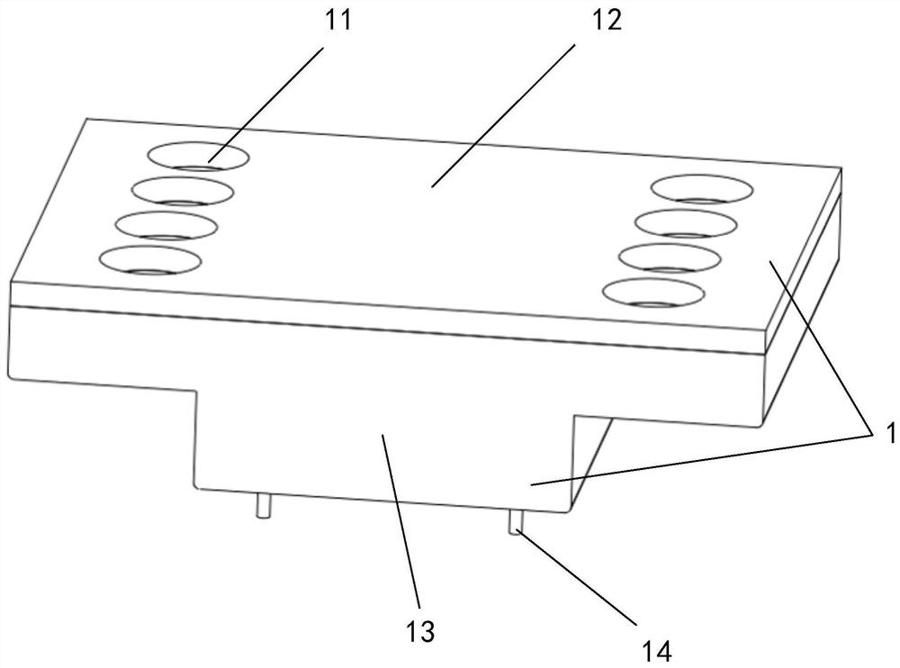
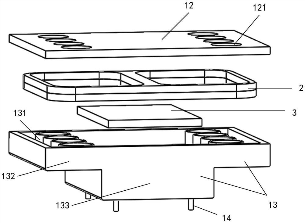
[0053] Embodiments of the present invention provide a fluxgate current sensor (current sensor for short), such as figure 1 As shown, the current sensor includes a housing 1 . The housing 1 is provided with a magnetic field induction device 2 and a signal conditioning circuit 3 .

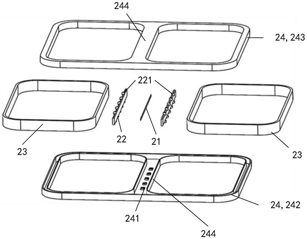
[0054] The magnetic field sensing device 2 include...


PUM


Abstract

The invention provides a fluxgate current sensor and a current measurement method. The fluxgate current sensor includes: an auxiliary magnetic core and at least two closed-loop magnetic circuits; the closed-loop magnetic circuits are symmetrically coupled; the auxiliary magnetic core is arranged in the closed-loop magnetic circuit. Magnetic circuit coupling connection. The fluxgate current sensor of the present invention has a symmetrically coupled closed-loop magnetic circuit, which can provide a magnetic field environment for symmetrical measurement, reduce the influence of high-order harmonics caused by the position of the eccentric conductor, reduce the production error between different sensors, and improve the measurement accuracy. .

Description

technical field [0001] The invention belongs to the technical field of power electronics, and particularly relates to a fluxgate current sensor and a current measurement method. Background technique [0002] A current sensor based on the principle of fluxgate is a magnetic field sensing device that is acted by an external magnetic field, an auxiliary driving magnetic field generated by an alternating current, and a compensating magnetic field generated by a feedback current, and can generate excitation signals for obtaining external magnetic field information. When the excitation signal is only driven by the auxiliary alternating current, the positive and negative directions are symmetrical. Under the action of the external magnetic field, the asymmetry of the excitation signal is related to the magnitude and direction of the external magnetic field, and the vector information of the external magnetic field is fed back and read by the compensation magnetic field to eliminate...

Claims


Application Information

Patent Timeline
Patent Type & Authority Patents(China)
IPC IPC(8): G01R19/00G01R15/20
CPCG01R19/0092G01R15/202
Inventor 万宇昭刘国安苑晓明万静龙张德光王玲
Owner HEFEI ECRIEE TAMURA ELECTRIC
Learn More