Monitoring system with photoelectric sensor and monitoring method

A photoelectric sensor and monitoring system technology, applied in the direction of color/spectral characteristic measurement, instruments, measuring devices, etc., can solve the problems that the state value and intermediate quantity are not an intuitive value, affect data statistics, and poor appearance color, etc., to achieve convenience The effect of monitoring statistics, saving labor, and reducing trial and error rates

Pending Publication Date: 2022-04-12
苏州优斯登物联网科技有限公司
View PDF5 Cites 0 Cited by
  • Summary
  • Abstract
  • Description
  • Claims
  • Application Information

AI Technical Summary

Problems solved by technology

[0003] However, there are also defects in the application of this analog quantity: first, what is read through the analog quantity is an intermediate quantity, and this intermediate quantity needs to be converted, oscilloscope and other means to indirectly obtain the corresponding state value indicating the distance; Or, neither the state value nor the intermediate value is an intuitive value, which cannot be further used for data analysis, which will affect the smooth progress of later data statistics and error analysis.
[0004] Furthermore, in the actual application environment, the existing displacement monitoring system only controls the switching value limit. When the color of the components is scattered, dust is generated, or the components are scratched on the work station and the appearance color is bad, it is very difficult to detect the aging of the optical fiber. Misjudgment will occur, resulting in reduced detection accuracy

Method used


Image

  • Monitoring system with photoelectric sensor and monitoring method
  • Monitoring system with photoelectric sensor and monitoring method
  • Monitoring system with photoelectric sensor and monitoring method

Examples


Embodiment 1

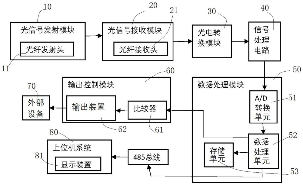
[0041] The present invention mainly provides a monitoring system with a photoelectric sensor. In one embodiment, the monitoring principle of the monitoring system of the present invention can be summarized as follows: the optical fiber transmitting head sends out a constant optical signal of a specific wavelength, which is received by the optical fiber receiving head. After the signal is converted into an electrical signal by the photoelectric conversion module, it is sent to the high-speed AD module of the MCU for sampling, and then the data is processed and stored in the storage unit, and the data can also be uploaded to the host computer system through the data bus. The optical signal received by the optical fiber receiving head is converted into an electrical signal by the photoelectric conversion module, and the switching value control signal is output by comparing with the set threshold.

[0042] In one embodiment, the working state of the monitoring system of the present...

Embodiment 2

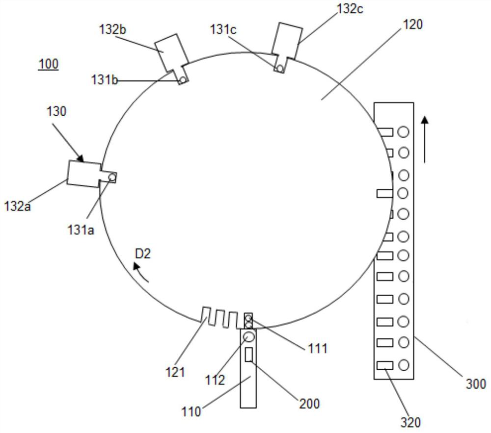
[0063] On the other hand, the monitoring system of the present invention can also be used to detect the existence of the workpiece on the station, such as whether the front and back of the workpiece are reversed (generally applicable to workpieces with different colors on the front and back), and when the workpiece enters the component processing equipment Before feeding, the workpieces need to be picked out from the material pile, and the workpieces should be arranged in a row facing up, and then the workpieces arranged in a row will enter the feeding station of the component processing equipment.

[0064]In one embodiment, several workpieces can be passed between the optical fiber receiving head 21 and the optical fiber emitting head 11 in sequence (the workpieces that are about to be arranged in a row pass through the optical fiber receiving head 21 and the optical fiber emitting head 11 successively. between inspections), the colors of the several workpieces are different f...

Embodiment 3

[0069] The present invention also provides a monitoring method of a monitoring system with a photoelectric sensor, which includes:

[0070] The optical fiber receiving head 21 receives the optical signal sent from the optical fiber emitting head 11, and transmits the optical signal to the photoelectric conversion module 30, and the photoelectric conversion module 30 converts the optical signal into an electrical signal, and the electrical signal is processed by signal processing. The circuit 40 performs signal processing to obtain an analog signal, the analog signal is converted into a digital signal by the data processing module 50, and the digital signal is compared with the reference signal after being received by the output control module 60, and the output control module 60 according to The comparison result sends out a switching value control signal, and the data processing module 50 monitors the change curve of the digital signal in real time, and displays the change cur...


PUM


Abstract

The invention discloses a monitoring system with a photoelectric sensor and a monitoring method thereof.The monitoring system comprises an optical signal receiving module, a photoelectric conversion module, a data processing module and an output control module, and the optical signal receiving module transmits received optical signals to the photoelectric conversion module; the photoelectric conversion module converts the optical signal into an electric signal, the electric signal is transmitted to the data processing module after being processed, the electric signal is converted into a digital signal through the data processing module, and the optical signal received by the optical signal receiving module changes along with the change of a measured physical quantity. The optical signal is converted into a digital signal, the digital signal is processed by the data processing module, the change rule of the measured physical quantity is displayed through a state change curve by the display device, and the monitoring system can be suitable for distance monitoring of high-precision equipment; and whether the appearance color of the product is qualified can be detected.

Description

technical field [0001] The invention relates to a sensor monitoring system applied in the field of automation, in particular to a monitoring system and a monitoring method with a photoelectric sensor. Background technique [0002] As a detection device, the sensor converts the measured physical quantity into an electrical signal, so as to realize the reprocessing of the obtained information through transmission, processing, storage, display, recording and control in the later stage. Taking the existing displacement sensor as an example, it detects the displacement by using the principle of cross-radiation of light, and obtains the displacement analog value, which can be used as a switch simply by using the analog value. For example, when the detected distance is close to the preset After the threshold range, the corresponding PLC device action will be controlled; for more complex applications, the analog quantity can play a role in monitoring statistics, for example, the ana...

Claims


Application Information

Patent Timeline
Patent Type & Authority Applications(China)
IPC IPC(8): G01B11/02G01N21/25
Inventor 黄德根
Owner 苏州优斯登物联网科技有限公司
Why Eureka
Try Eureka