
Balanced metal detection device and method based on matrix coil

A metal detection, balanced technology, applied in measuring devices, radio wave measurement systems, electrical/magnetic exploration, etc., can solve problems such as production occasions that cannot be processed with bulk raw materials, to overcome strong electromagnetic interference and ensure detection. Accuracy, the effect of increasing the detection height

Active Publication Date: 2021-09-03
WEIFANG HUAQIANG ELECTROMAGNETIC EQUIP CO LTD
View PDF8 Cites 0 Cited by
  • Summary
  • Abstract
  • Description
  • Claims
  • Application Information

AI Technical Summary

Problems solved by technology

Existing metal detection methods generally install a transmitting coil and a receiving coil on the upper and lower sides of the detection area. The distance between the two coils does not exceed 0.6 meters, which cannot be applied to production occasions where large raw materials are processed.

Method used


Image

  • Balanced metal detection device and method based on matrix coil
  • Balanced metal detection device and method based on matrix coil
  • Balanced metal detection device and method based on matrix coil

Examples


Embodiment 1

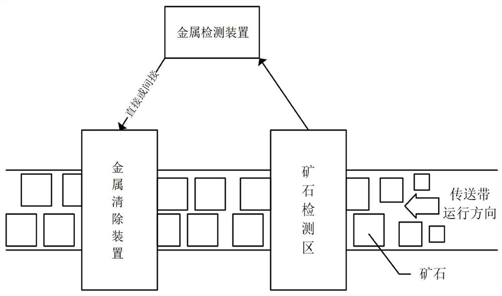
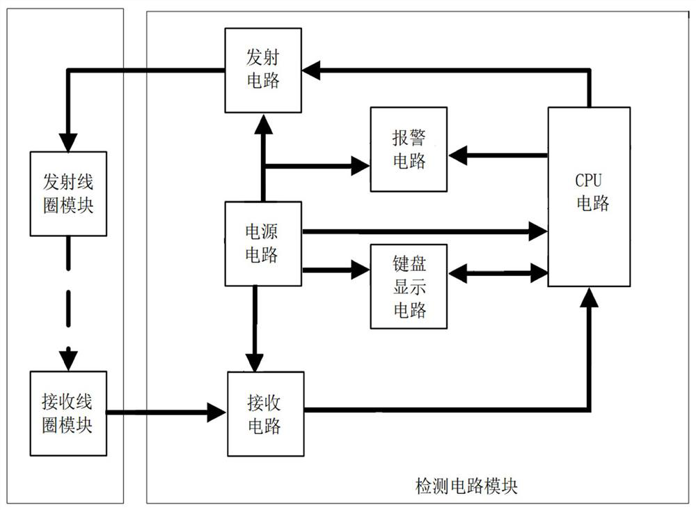
[0042] Such as figure 1 and figure 2 Commonly shown, a balanced metal detection device based on a matrix coil is installed in the ore detection area to detect whether there is a metal detection object in the ore raw material, and to directly or indirectly control the metal removal device. A balanced metal detection device based on matrix coils includes a detection circuit module, a transmitting coil module, and a receiving coil module that are electrically connected to each other.

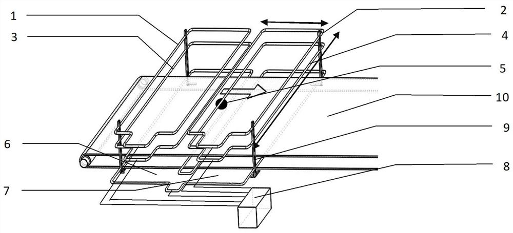
[0043] Such as figure 2 and image 3Commonly, as shown, the detection circuit module 8 is composed of a casing (not shown in the figure) and an internal circuit board. The shell is made of metal material, and the width, height, and depth of the shell are 45*70*30mm respectively. It is installed on one side of the conveyor belt 10 and connected with the transmitting coil module and the receiving coil module by wire. The internal circuit board includes a CPU circuit and a transmitting circuit, ...

Embodiment 2

[0055] The detection method formed by a balanced metal detection device based on matrix coils described in Embodiment 1 includes the following steps:

[0056] S1. The CPU circuit generates a continuous wave excitation signal to the transmitting circuit, and the continuous wave excitation signal generated by the transmitting circuit is output to the transmitting coil module. The transmitting coil module sends four continuous wave excitation signals in groups, and the receiving coil module receives the induced electromotive force EMF of the metal detection object. signal and transmit it to the receiving circuit.

[0057] S2. The receiving circuit receives the induced electromotive force EMF signal of the metal detection object obtained by the receiving coil module, performs differential calculation, circuit conditioning, two-stage amplification and filtering on the obtained signal, and then sends it to the CPU circuit for calculation.

[0058] S3. The CPU circuit converts the re...


PUM


Abstract

The invention discloses a balanced metal detection device and method based on a matrix coil, and relates to the technical field of metal detection equipment. The balanced metal detection device comprises a detection circuit module, a transmitting coil module and a receiving coil module which are electrically connected with one another; the detection circuit module is located on one side of a conveying belt, and the transmitting coil module is located on the upper portion of the conveying belt; the receiving coil module is located on the lower portion of the conveying belt, the transmitting coil module comprises a plurality of sets of transmitting coils which are arranged in a multi-layer and multi-column matrix type structure, the transmitting coils are fixed to coil supports, and the coil supports are fixed to the two sides of the conveying belt. In the space structure, the multi-layer structure of the transmitting coil is used for gathering magnetic line distribution, reducing leakage magnetic flux, increasing the detection distance of a metal detection object and ensuring the detection precision; the multi-group structure of the transmitting coil is used for distinguishing the shape and size of a metal detection object.

Description

technical field [0001] The invention relates to the technical field of metal detection equipment, in particular to a balanced metal detection device and method based on matrix coils. Background technique [0002] Metal detection devices are widely used in food, raw material processing, public safety and other fields, especially in industrial and mining enterprises. The difference from other fields is that the environment of industrial and mining sites is complex and harsh. There are not only strong electromagnetic interference from various high-power equipment, but also various harsh on-site environments such as vibration, high temperature, low temperature, and dust. At the same time, in order to meet their own production capacity needs, industrial and mining enterprises continue to expand the volume of raw materials, which requires a substantial increase in the height of the detection coil, resulting in a decrease in the signal-to-noise ratio of the metal detection device a...

Claims


Application Information

Patent Timeline
Patent Type & Authority Applications(China)
IPC IPC(8): G01V3/11
CPCG01V3/104
Inventor 刘宇魏东张立清
Owner WEIFANG HUAQIANG ELECTROMAGNETIC EQUIP CO LTD
Learn More