
Sensing optical cable for optical fiber current transformer

A technology for sensing optical cable and optical fiber current, which is applied in the direction of cladding optical fiber, current-only measurement, optical waveguide and light guide, etc. It can solve the problems of inconvenient use and installation of fixed sensing rings, large and irregular conductors to be tested, and achieve Compact structure, simple structure, convenient and flexible installation

Active Publication Date: 2021-09-03
YANGTZE OPTICAL FIBRE & CABLE CO LTD
View PDF8 Cites 2 Cited by
  • Summary
  • Abstract
  • Description
  • Claims
  • Application Information

AI Technical Summary

Problems solved by technology

[0003] As a new type of electronic current sensing system, the optical fiber current transformer is based on the principle of measuring the current by demodulating the interference signal carrying the phase difference information of left-handed circularly polarized light and right-handed circularly polarized light in a magnetic field environment. The commonly used optical fiber current transformer sensor head is a fixed sensor ring structure. In actual engineering use and installation, sometimes it is necessary to repeatedly load and unload to measure the current at different positions of the busbar. Some conductors to be tested are large in size or irregular. It is very inconvenient to use and install the fixed sensor ring

Method used


Image

  • Sensing optical cable for optical fiber current transformer
  • Sensing optical cable for optical fiber current transformer
  • Sensing optical cable for optical fiber current transformer

Examples


Embodiment Construction

[0021] The present invention will be further described below in conjunction with drawings and embodiments.

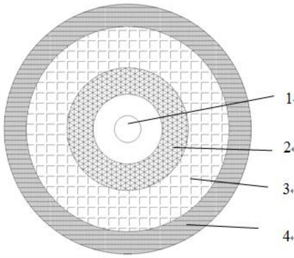
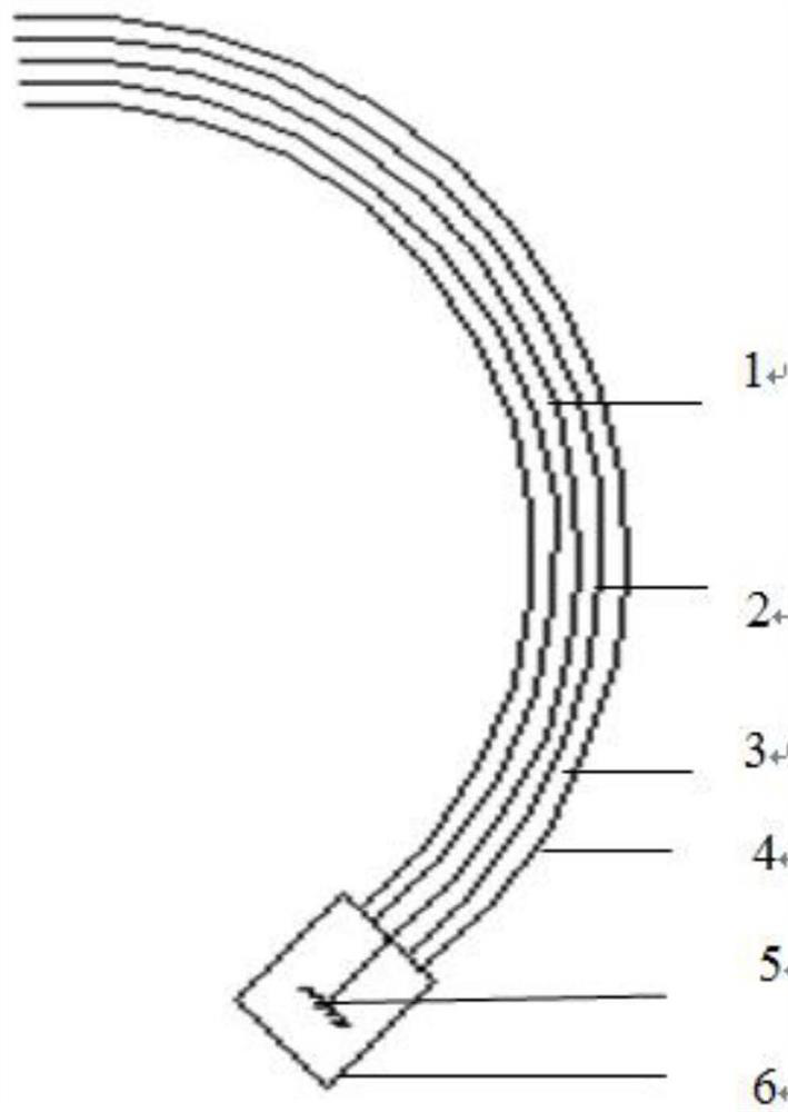
[0022] It includes an outer sheath 4 and an optical fiber. The outer sheath is a halogen-free wear-resistant and flame-retardant outer sheath, which has the characteristics of softness, wear resistance, corrosion resistance, and flame retardancy. The outer sheath is equipped with an optical fiber. The said The optical fiber is a circular optical fiber 1. The circular optical fiber is a rotating high-birefringence optical fiber, and its stress zone is uniformly and densely twisted. The optical fiber is made by rotating a high-stress polarization-maintaining preform or a linear birefringent optical fiber around the axis. The optical fiber Because it has a certain circular birefringence and can resist the additional line birefringence caused by bending and torsion, it becomes an ideal sensor for optical fiber current sensors. The rotation period of the circular optical fibe...


PUM


Abstract

The invention relates to a sensing optical cable for an optical fiber current transformer, which comprises an outer sheath and an optical fiber, and is characterized in that the optical fiber is a round-keeping optical fiber, a quartz sleeve is sleeved outside the round-keeping optical fiber, the outer sheath is coated outside the quartz sleeve, a reflecting mirror is arranged at the end of the round-keeping optical fiber at one end of the optical cable, and an end socket is arranged. When the sensing optical cable is used, the optical cable and the end socket end are wound on the conductor to serve as a detection sensing end, the other end of the optical cable is connected with the modulation detection device, compared with a fixed sensing ring structure, the sensing optical cable can be wound on the conductor on site, and the sensing optical cable has the advantages of being convenient and flexible to use and install and high in environmental adaptability. The device is simple in structure and reasonable in arrangement, the arrangement of the quartz sleeve can avoid the influence of the stress and temperature of the round-keeping optical fiber, and the measurement accuracy of the device is ensured.

Description

technical field [0001] The invention relates to a sensing optical cable used for an optical fiber current transformer, belonging to the technical field of high-voltage electric power measurement. Background technique [0002] With the comprehensive construction of smart grids at home and abroad, the grid has higher and higher requirements for informatization, automation, interactivity and rapid response. Traditional electromagnetic current transformers have gradually exposed principle defects, such as large , poor anti-electromagnetic interference ability, large material loss, poor insulation performance and other shortcomings, it is difficult to adapt to the needs of power grid development. As a passive electronic current transformer, the all-fiber current transformer has outstanding advantages in adapting to high-voltage power grid measurement, informatization and fast response, such as relatively simple insulation, no ferromagnetic saturation, good transient characteristi...

Claims


Application Information

Patent Timeline
IPC IPC(8): G02B6/44G02B6/02G02B6/26C03B37/027G01R19/00G01R15/24
CPCG02B6/443G02B6/02076G02B6/02123G02B6/4436G02B6/4486G02B6/262C03B37/02709C03B37/02745G01R19/0092G01R15/245C03B2205/07C03B2205/40
Inventor 彭慎张心贲胡蓓王亮张广博徐峰陶金金曹蓓蓓
Owner YANGTZE OPTICAL FIBRE & CABLE CO LTD
Learn More