Commutator forming mold

A technology for forming molds and commutators, applied in the field of commutators, can solve problems such as vaporization, copper sheet deformation, and physical injury to operators, and achieve the effects of maintaining permeability, improving efficiency, and facilitating cleaning

Active Publication Date: 2021-09-03
GUANGZHOU GRG LAMKO MOLD MFG
View PDF6 Cites 0 Cited by
  • Summary
  • Abstract
  • Description
  • Claims
  • Application Information

AI Technical Summary

Problems solved by technology

[0006]Aiming at the above-mentioned shortcomings existing in the prior art, the present invention provides a commutator molding die, which can effectively solve the problem of the traditional commutator copper During the demoulding process, due to manual operation, the force on the bottom of the copper sheet is uneven, which may easily cause local deformation of the copper sheet and reduce the quality of the commutator. Problems that cause great bodily harm

Method used


Image

  • Commutator forming mold
  • Commutator forming mold
  • Commutator forming mold

Examples


Embodiment

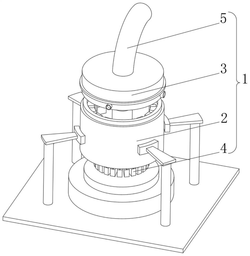
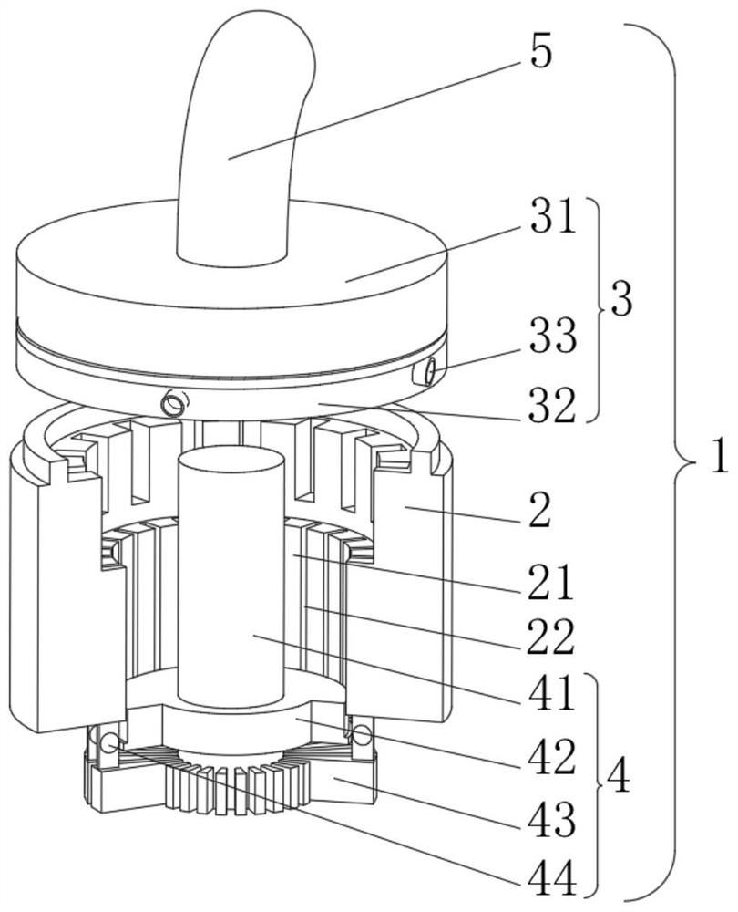
[0040] Embodiment: A kind of commutator molding mold, comprises the commutator injection molding mold body 1 that fixed mold 2, movable mold 3, ejector 4 and exhaust pipe 5 are formed, the bottom of movable mold 3 and the bottom of fixed mold 2 The top is threaded, the demoulding device 4 is located inside the fixed mold 2, the bottom end of the suction pipe 5 is connected with the inside of the movable mold 3, the top of the suction pipe 5 is connected with the external air extractor, and the inside of the fixed mold 2 is respectively opened There are injection molding holes 21 and injection molding grooves 22. The stripper 4 includes a middle solid rod 41. The bottom of the middle solid rod 41 is fixedly connected with a limit plate 42. The outer side of the limit plate 42 is slidingly connected with the inner wall of the injection hole 21. The limit plate The bottom of 42 is fixedly connected with lifting plate 43, the bottom of lifting plate 43 is fixedly connected with the...


PUM


Abstract

The invention relates to the technical field of commutators, in particular to a commutator forming mold. The mold comprises a commutator pressure injection forming mold body composed of a fixed mold body, a movable mold body, a demolding device and an exhaust pipe, the bottom of the movable mold body is in threaded connection with the top of the fixed mold body, the demolding device is located in the fixed mold body, the bottom end of the exhaust pipe is communicated with the interior of the movable mold body, the top end of the exhaust pipe communicates with an external air extractor, an injection molding hole and an injection molding groove are formed in the fixed mold body, the demolding device comprises a middle fixing rod, and the bottom of the middle fixing rod is fixedly connected with a limiting plate. The commutator forming mold solves the problems that: in the demolding process of a traditional commutator copper sheet, due to manual operation, stress at the bottom of the copper sheet is uneven, local deformation of the copper sheet is likely to happen, the quality of a commutator is reduced, and meanwhile in the copper sheet pouring process, a large amount of copper-containing gas is vaporized, and great harm is caused to the body of an operator.

Description

technical field [0001] The present invention relates to the field of commutator technology, in particular to a commutator molding die. Background technique [0002] Commutator, also known as "commutator". An important component on the motor armature of DC motors and AC commutators. A plurality of copper sheets separated by mica sheets form a cylinder or a disc shape, and each copper sheet is connected to certain armature winding elements. When the armature rotates, the copper sheets successively contact the fixed brushes. In a DC motor, the alternating current in the armature winding is converted into direct current between the brushes through the brushes and the commutator. In the AC commutator motor, the frequency of the alternating current between the brushes meets the working requirements. [0003] According to Chinese patent CN102709787A, an automatic demoulding method for commutator injection mold: put molding compound in the material chamber plate, install commuta...

Claims


Application Information

Patent Timeline
IPC IPC(8): H01R43/06
CPCH01R43/06
Inventor 杨阿东
Owner GUANGZHOU GRG LAMKO MOLD MFG
Why Eureka
Try Eureka