
Module power supply packaging structure

A packaging structure and module power supply technology, which can be used in power supply testing, circuit heating devices, and electrical measurement. It can solve problems such as cable breakage, lack of power module packaging structure, and poor contact, so as to reduce volume, ensure efficient operation, The effect of improving productivity

Inactive Publication Date: 2021-09-03
广州市爱浦电子科技有限公司
View PDF0 Cites 0 Cited by
  • Summary
  • Abstract
  • Description
  • Claims
  • Application Information

AI Technical Summary

Problems solved by technology

[0003] In the existing power module, there are the following problems: First, the devices on the pcb assembly are in the mode of cable connection. When the potting glue is used to pot it, it is very easy to cause the cable to appear due to the pressure impact of the potting glue. In the case of breakage or poor contact; secondly, the shell needs to be made separately, and the shell is used to carry the pcb components and the potting compound, and finally potted to form an integrated power module
[0004] Therefore lack a kind of power module encapsulation structure that can reduce above-mentioned problem

Method used


Image

  • Module power supply packaging structure
  • Module power supply packaging structure
  • Module power supply packaging structure

Examples


Embodiment Construction

[0059] The preferred embodiments of the present invention will be described below in conjunction with the accompanying drawings. It should be understood that the preferred embodiments described here are only used to illustrate and explain the present invention, and are not intended to limit the present invention.

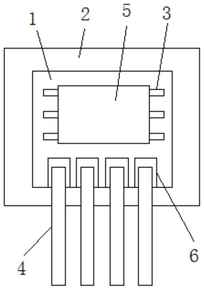
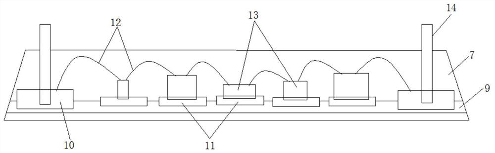
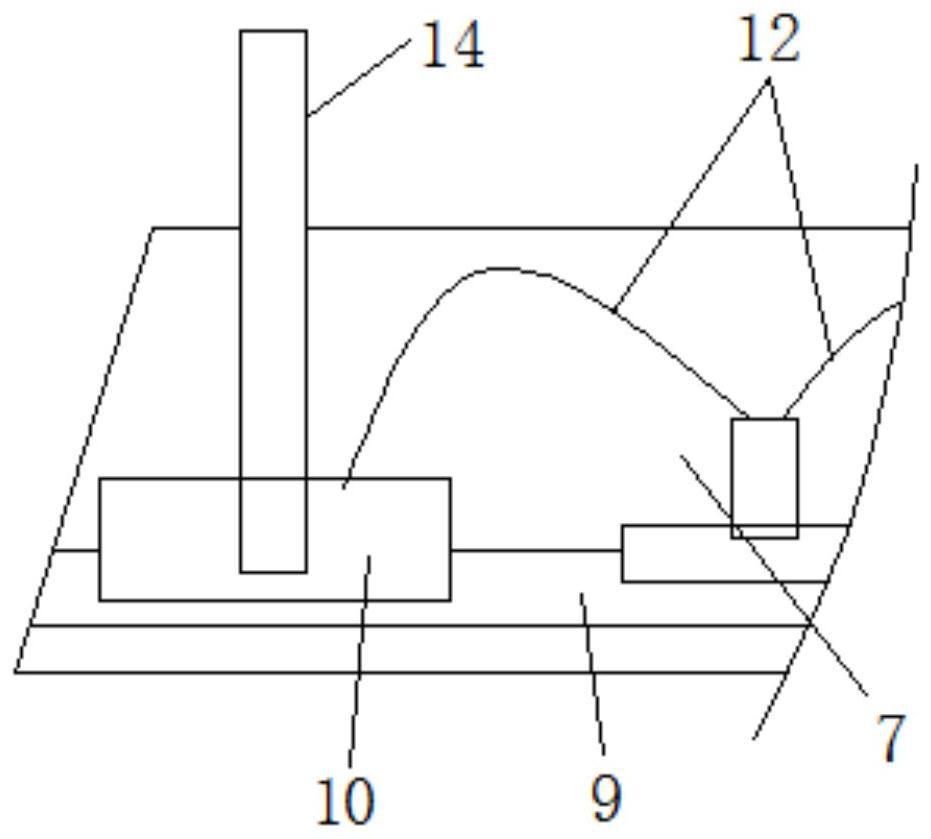
[0060] according to Figure 1-9 As shown, the embodiment of the present invention provides a module power packaging structure, including: PCB components and potting glue 2,

[0061] The outer periphery of the PCB assembly is covered with potting glue 2, and the PCB assembly is provided with a plurality of pins 4, and the end of each pin 4 away from the PCB assembly is outward from the potting glue 2 extend.

[0062] The PCB assembly includes: a PCB board 1, on which a printed circuit is arranged, and the printed circuit is used to electrically connect with the power chip 5 and the pin 4 respectively.

[0063] The printed circuit includes a plurality of first pads ...


PUM


Abstract

The invention provides a module power supply packaging structure, and the structure comprises a PCB assembly and a pouring sealant; the periphery of the PCB assembly is coated with the pouring sealant, the PCB assembly is provided with a plurality of pins, and one end, far away from the PCB assembly, of each pin extends outwards from the pouring sealant. According to the module power supply packaging structure provided by the invention, in the manufacturing process of the power supply module, firstly, a chip type power supply chip is used for replacing a traditional cable type power supply module, so the condition that the yield of the power supply module is low due to poor cable connection of the cable type power supply module is reduced; secondly, a shell is omitted, when the power supply module is manufactured, the manufacturing cost, the inventory storage cost and the maintenance cost of the shell can be reduced, and the heat dissipation efficiency of the module power supply can also be improved; in addition, the purpose of machine automatic welding is achieved through the chip type power supply chip, the situation of traditional manual cable welding is reduced, and the production efficiency is improved.

Description

technical field [0001] The invention relates to the technical field of electronic products, in particular to a module power packaging structure. Background technique [0002] At present, the power module is a common electronic component, which mainly includes shell components, PCB components and potting glue; when making, it first puts the pcb component in the shell, then fills the shell with potting glue, and finally puts the The shell filled with potting glue is left to stand and solidified to form a power module; [0003] In the existing power module, there are the following problems: First, the devices on the pcb assembly are in the mode of cable connection. When the potting glue is used to pot it, it is very easy to cause the cable to appear due to the pressure impact of the potting glue. In the case of breakage or poor contact; secondly, the shell needs to be made separately, and the shell is used to carry the pcb component and the potting compound, and finally potted...

Claims


Application Information

Patent Timeline
IPC IPC(8): H05K5/06H05K1/02H05K1/18H05K5/02G01R31/28G01R31/40
CPCH05K5/065H05K1/181H05K1/0209H05K5/0247G01R31/40G01R31/2843
Inventor 李绍兵韦辉
Owner 广州市爱浦电子科技有限公司
Learn More