
Semiconductor-based cooling condensation vegetation drip irrigation device

A semiconductor and vegetation technology, applied in refrigerators, watering devices, refrigeration and liquefaction, etc., can solve the problems of single working mode, low heat transfer coefficient, low water production, etc., and achieve the effect of increasing air intake and water intake efficiency

Active Publication Date: 2022-06-28
WUHAN UNIV OF TECH
View PDF10 Cites 0 Cited by
  • Summary
  • Abstract
  • Description
  • Claims
  • Application Information

AI Technical Summary

Problems solved by technology

At present, the water intake device of the adsorption analysis method needs to install a light-transmitting cover during the day and remove it at night. The workload is heavy. The replacement cycle of the adsorbent is 6 months, and the maintenance cost is high.
At present, there are the following problems in the water intake device of cooling condensation method relying on semiconductors: relying on natural air intake, the incoming air is less, that is, the air with high humidity is less, so the water production speed is slow; on the surface of the semiconductor cold end fins, it is easy to form Film condensation, the low heat transfer coefficient makes the condensation speed slow. In addition, the droplets produced by this condensation method are not easy to fall off and collect, and are easy to frost, which affects the subsequent condensation of water vapor that continues to enter, so the water production is low; It is used for fresh water production and has a single working mode. It lacks specific designs suitable for realistic scenarios such as sandy land afforestation, so its practical application value is not great

Method used


Image

  • Semiconductor-based cooling condensation vegetation drip irrigation device
  • Semiconductor-based cooling condensation vegetation drip irrigation device
  • Semiconductor-based cooling condensation vegetation drip irrigation device

Examples


Embodiment Construction

[0035]The implementation of the present invention will be described in detail below in conjunction with the accompanying drawings, but they do not constitute a limitation of the present invention, but are merely examples, and at the same time, the advantages of the present invention will be more clearly understood through the description. All modifications that those skilled in the art can directly derive or associate from the disclosed content of the present invention should be considered as the protection scope of the present invention. The positional relationships described in the embodiments are consistent with those shown in the drawings, and other parts not described in detail in the embodiments are in the prior art.

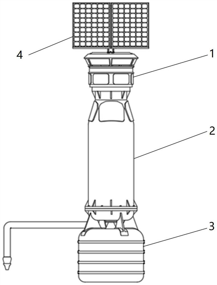
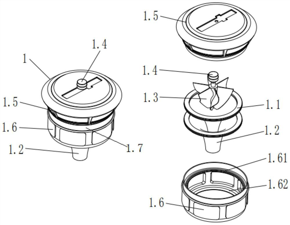
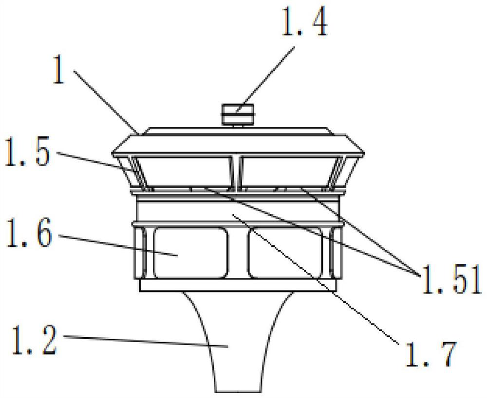
[0036] like figure 1 The drip irrigation device shown is composed of a dual-stage air induction module 1, a refrigeration water intake module 2, a water storage drip irrigation module 3 and a solar panel 4. The solar panel 4 is installed on the top of the ...


PUM


Abstract

The present invention proposes a semi-conductor-based refrigeration condensation vegetation drip irrigation device. In the double-stage air induction module, a double-layer Venturi structure is adopted, combined with a fan to increase the air intake; in the refrigeration water intake module, the outer wall of the inner pipe at the cold end is set The semiconductor chip in the semiconductor chip module is connected to the circuit control module that can control the temperature of the inner tube at the cold end, so that the temperature of the inner tube at the cold end is kept within a reasonable range above the frost point temperature of water and below the dew point temperature, which solves the problem of cold The problem that the surface of the inner wall of the inner pipe at the end is easy to frost has greatly improved the water intake efficiency of the drip irrigation device; The set water pump is connected to the water pipe to realize drip irrigation; the drip irrigation device is powered by the electric energy obtained by the solar panel, and can run automatically for a long time, which is extremely suitable for vegetation drip irrigation in arid areas.

Description

technical field [0001] The invention belongs to the technical field of irrigation devices, and designs a drip irrigation device for refrigerating dew condensation vegetation. Background technique [0002] For semi-arid areas, green vegetation needs to be irrigated during the growth process, but the water resources in the area are scarce, and the transportation of water resources from other areas for irrigation is expensive. Therefore, air water intake systems are generally used to irrigate green vegetation. [0003] At present, the air water intake technology is mainly divided into: adsorption analysis method and refrigeration condensation method. At present, the water intake device of the adsorption analysis method needs to install a light-transmitting cover during the day and remove it at night, which requires a large workload. The replacement cycle of the adsorbent is 6 months, and the maintenance cost is high. At present, there are the following problems in the refriger...

Claims


Application Information

Patent Timeline
Patent Type & Authority Patents(China)
IPC IPC(8): F25B21/02A01G25/02
CPCA01G25/023F25B21/02Y02A40/22
Inventor 吴彦春陈光宇周霖黄姝笛宋飞
Owner WUHAN UNIV OF TECH
Learn More