
Frostless condensation heat regeneration type solution dehumidification aircraft ground air conditioning box

A solution dehumidification and air-conditioning box technology, applied in refrigerators, heating methods, air-conditioning systems, etc., can solve the problems of easy frosting and energy consumption of evaporators, and achieve the effects of convenient operation, stable output cooling capacity, and reduced heat consumption.

Inactive Publication Date: 2016-02-17
HARBIN INST OF TECH
View PDF10 Cites 0 Cited by
  • Summary
  • Abstract
  • Description
  • Claims
  • Application Information

AI Technical Summary

Problems solved by technology

[0004] The invention aims to solve the problem that the evaporator is easy to frost and consumes a lot of energy during the operation of the traditional aircraft air conditioning unit, and provides a frost-free condensation heat regeneration type solution dehumidification aircraft ground air conditioning unit

Method used


Image

  • Frostless condensation heat regeneration type solution dehumidification aircraft ground air conditioning box
  • Frostless condensation heat regeneration type solution dehumidification aircraft ground air conditioning box
  • Frostless condensation heat regeneration type solution dehumidification aircraft ground air conditioning box

Examples


specific Embodiment approach 1

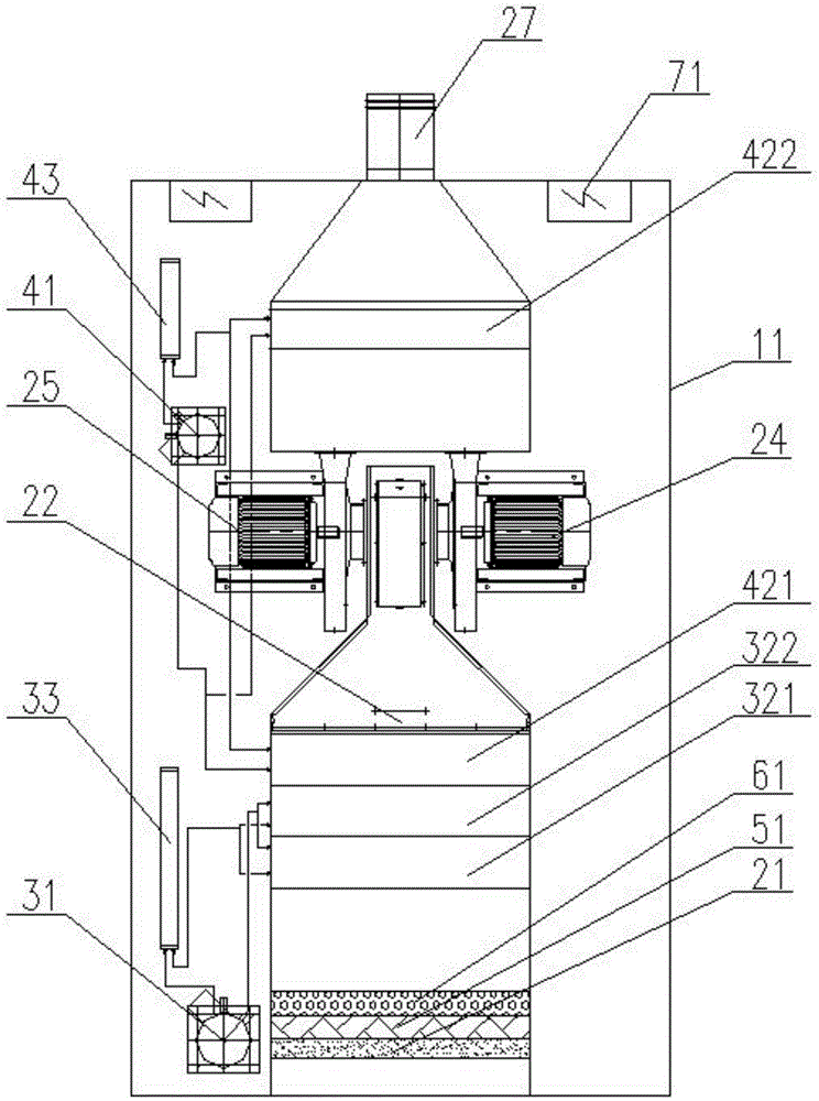
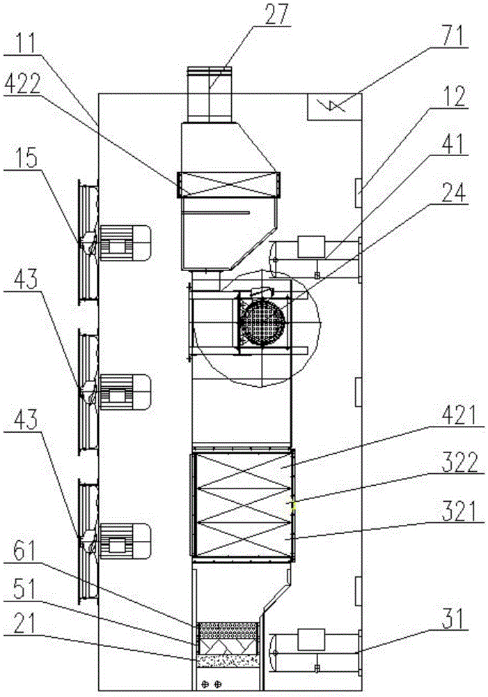
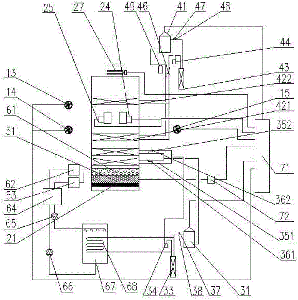
[0016] Specific implementation mode one: as figure 1 As shown, a frost-free condensation heat regeneration type solution dehumidification aircraft ground air conditioning box in this embodiment includes a frame 11, an air-conditioning air supply system, a solution dehumidification system 61, a refrigeration system, a heating system and an automatic control system; The system includes a first high-pressure blower 24, a second high-pressure blower 25, a filter 21, an air duct 22 and an air outlet 27; the solution dehumidification system 61 includes a concentrated solution tank 62, a dilute solution tank 63, a heat exchange box 64, a dilute solution pump 65, concentrated solution pump 66 and evaporative condensation regenerator 67; the refrigeration system includes a first compressor 31, a first front-stage evaporator 321, a first rear-stage evaporator 322, a first condenser 33, a first Liquid reservoir 34, pre-stage dry filter 351, post-stage dry filter 352, pre-stage expansion ...

specific Embodiment approach 2

[0017]Specific embodiment 2: The difference between this embodiment and specific embodiment 1 is that: one side of the side wall of the frame 11 is provided with a ground-mounted mounting seat 12, and the other side of the side wall of the frame 11 is sequentially from top to bottom The third axial flow fan 15, the second axial flow fan 14 and the first axial flow fan 13 are provided; the third axial flow fan 15, the second axial flow fan 14 and the first axial flow fan 13 and the electrical control box 71 connected. Others are the same as the first embodiment.

specific Embodiment approach 3

[0018] Embodiment 3: This embodiment differs from Embodiment 1 or Embodiment 2 in that: the dehumidifier 61 adopts the method of spraying tower cloth liquid, and the tower is filled with fillers. Others are the same as those in Embodiment 1 or 2.


PUM


Abstract

The invention discloses a frostless condensation heat regeneration type solution dehumidification aircraft ground air conditioning box, relates to the frostless condensation heat regeneration type solution dehumidification aircraft ground air conditioning box, and solves the problems of easy frosting of an evaporator and high energy consumption in the operation period of a traditional aircraft air conditioning unit. The frostless condensation heat regeneration type solution dehumidification aircraft ground air conditioning box comprises a frame, an air conditioning air supply system, a solution dehumidification system, a refrigeration system, a heating system and an automatic control system, wherein the air conditioning air supply system comprises a first high-pressure air blower, a second high-pressure air blower, a filter, an air way and an air supply port; the solution dehumidification system comprises a concentrate solution tank, a dilute solution tank 63, a heat exchange box, a dilute solution pump, a concentrate solution pump and an evaporation type condensation regenerator; and the refrigeration system comprises a compressor, an evaporator, a condenser, a liquid storer and a drying filter. The frostless condensation heat regeneration type solution dehumidification aircraft ground air conditioning box is applied to the air exchange of aircrafts in airports with larger heat-humidity ratio change and in high humidity regions.

Description

technical field [0001] The invention relates to a frost-free condensation heat regeneration type solution dehumidification aircraft ground air-conditioning box. Background technique [0002] In order to ensure the cooling capacity of the traditional aircraft ground air conditioning unit, the air outlet temperature is required to be as low as 1-4°C. During the operation, the evaporation temperature of the evaporator is lower than 0°C, which is easy to cause frost on the evaporator fins. The longer the run time, the worse the frost buildup. Frosting will block the fins of the evaporator, increase the air resistance of the evaporator, reduce the ventilation rate, and further reduce the evaporation temperature. Long-term continuous operation will easily cause low-pressure protection of the unit. It needs to be shut down to defrost before it can be turned on again. The temperature and cooling capacity become unstable due to frosting, and the air conditioner cannot provide stable...

Claims


Application Information

Patent Timeline
Patent Type & Authority Applications(China)
IPC IPC(8): F24F3/14F24F3/06F25B29/00F25B41/00B64F1/36
CPCF24F3/065F24F3/1429F25B29/003B64F1/362F24F2003/144F25B41/40
Inventor 倪龙姚杨李慧
Owner HARBIN INST OF TECH
Learn More