
Clamping device

A clamping device and clamping technology, applied in the field of manipulators, can solve the problems of complex structure of transmission components, many parts and components, high cost, etc., and achieve the effect of simple matching method, low cost and convenient assembly.

Pending Publication Date: 2021-09-07
XIAMEN HONGFA IND ROBOT CO LTD
View PDF0 Cites 0 Cited by
  • Summary
  • Abstract
  • Description
  • Claims
  • Application Information

AI Technical Summary

Problems solved by technology

However, with the increase of clamping components, the driving mechanism also needs to be increased, or the transmission assembly between the power component and the clamping component needs to be modified, resulting in a very complicated structure of the transmission assembly and a large number of parts used
Therefore, whether it is to increase the number of driving mechanisms or to modify the transmission components, problems such as high cost and large volume will occur

Method used


Image

  • Clamping device
  • Clamping device
  • Clamping device

Examples


Embodiment Construction

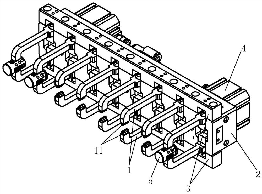
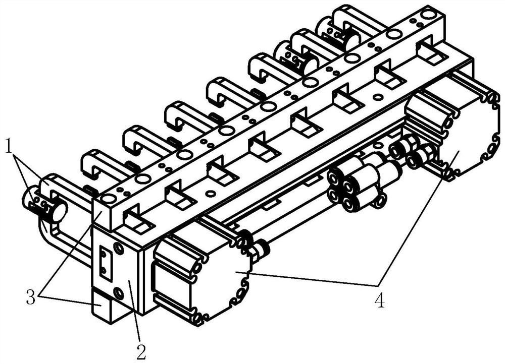
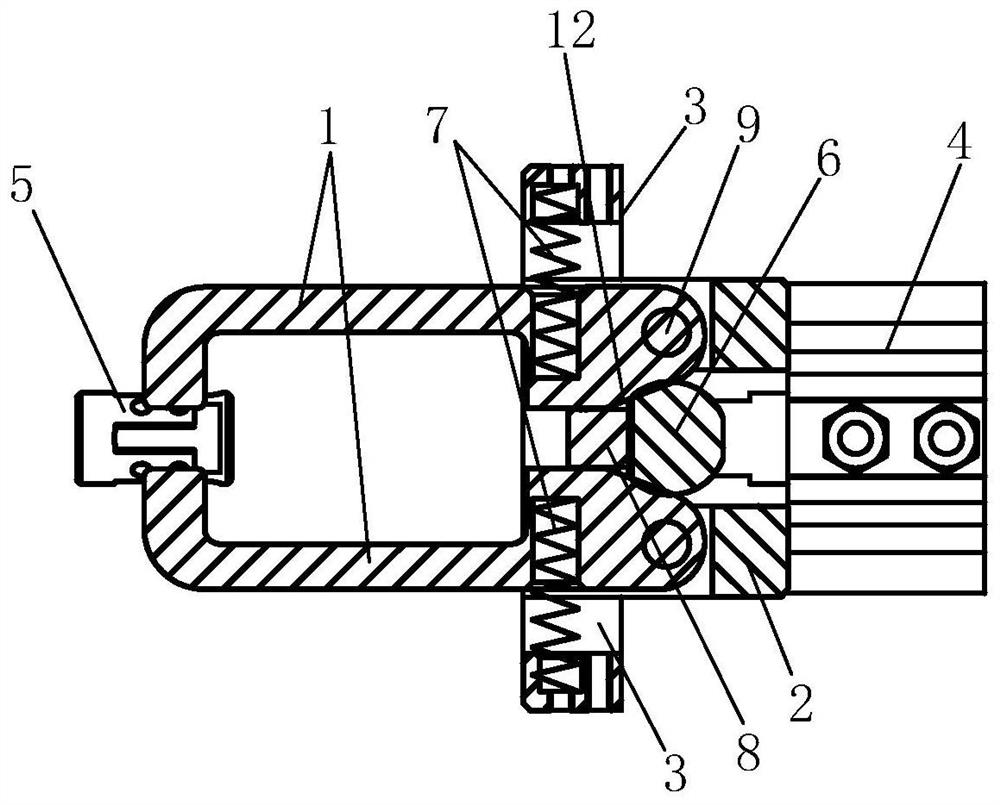
[0026] Examples, see Figure 1-Figure 4 As shown, a clamping device of the present invention includes a fixed body, a clamping unit, a power component, and a pusher 6. The clamping unit includes a plurality of clamping components distributed side by side, and each clamping component includes two clamping jaws 1 , the two jaws 1 are respectively rotatably connected to the fixed body, and the two jaws 1 are arranged oppositely; the power component is arranged on the fixed body, and pushes the two jaws 1 of each clamping part through the pusher 6 when starting, so that the two The clamping jaws 1 are used to separate one end of the clamping object from each other; the two clamping jaws 1 of each clamping part are respectively equipped with a reset part with the fixed body, or the two clamping jaws 1 of each clamping part are equipped with a reset part, and the reset The part drives the two jaws 1 to reset, so that the ends of the two jaws 1 for clamping the object are moved close...


PUM


Abstract

The invention discloses a clamping device which comprises a fixing body, a clamping unit, a power part and a pushing part, the clamping unit comprises a plurality of clamping parts distributed in parallel, each clamping part comprises two clamping jaws, the two clamping jaws are rotationally connected to the fixing body, and the two clamping jaws are oppositely arranged; the power part is arranged on the fixing body, and pushes the two clamping jaws of each clamping part through the pushing part when being started, so that the ends, used for clamping objects, of the two clamping jaws are separated from each other; and the two clamping jaws of each clamping part are matched with the fixing body to be provided with reset parts respectively, or the two clamping jaws of each clamping part are matched with reset parts, the reset parts drive the two clamping jaws to reset, and the ends, used for clamping objects, of the two clamping jaws are made to be close to each other. The synchronous opening and closing of the two clamping jaws of the multiple clamping parts can be controlled by adopting a small number of power parts and a simple transmission mode, so that the cost is greatly reduced, the structure of the whole device is simpler, the size is smaller, and the occupied space is reduced.

Description

technical field [0001] The invention relates to the technical field of manipulators, in particular to a clamping device. Background technique [0002] In the automatic assembly process, the clamping device is widely used in the clamping and transfer of various objects. The clamping device in the prior art generally includes two jaws, a driving mechanism, etc., and the driving mechanism includes a cylinder and a transmission assembly. closure. Generally, the clamping part composed of the two jaws can only clamp one or two products at a time. When multiple products need to be clamped, the usage requirement can only be met by increasing the number of clamping parts. However, with the increase of clamping components, the driving mechanism also needs to be increased, or the transmission assembly between the power component and the clamping component needs to be modified, resulting in a very complicated structure of the transmission assembly and a large number of parts used. T...

Claims


Application Information

Patent Timeline
Patent Type & Authority Applications(China)
IPC IPC(8): B25J15/10B65G47/90
CPCB25J15/10B65G47/90B65G47/907
Inventor 廖建明陈奕文白杰昌
Owner XIAMEN HONGFA IND ROBOT CO LTD
Learn More