
Micro fit clearance screw of plastic film extruder

A technology of plastic film and matching gap, which is applied in the field of micro-fitting screw, can solve the problems of accelerated aging of extruder barrel, low extrusion efficiency of extruder, waste of operating cost, etc., to reduce backflow phenomenon, shorten The effect of staying time and improving ability

Pending Publication Date: 2021-09-07
洛阳市大资塑业有限公司
View PDF5 Cites 0 Cited by
  • Summary
  • Abstract
  • Description
  • Claims
  • Application Information

AI Technical Summary

Problems solved by technology

The main technical problems of the plastic film extruder in the process of producing plastic film are: 1. Due to the long residence time of the molten polypropylene material in the extruder barrel, the rapid aging of the extruder barrel is accelerated (heat 2. The extrusion efficiency of the extruder is low, resulting in a waste of operating costs; 3. Since a die is provided at the discharge end of the extruder, a certain amount of time is required when using the die to extrude a plastic film At this time, the pressure in the barrel of the extruder will increase. The gap between the barrel and the screw of our company's extruder is 0.055mm (55 wires) before the improvement, resulting in the molten material in the barrel from Backflow occurs between the screw and the barrel; the inventor has developed a micro-fit gap screw for a plastic film extruder based on the above-mentioned defects in the prior art, which can well solve the above-mentioned problems in the prior art

Method used


Image

  • Micro fit clearance screw of plastic film extruder
  • Micro fit clearance screw of plastic film extruder
  • Micro fit clearance screw of plastic film extruder

Examples


Embodiment Construction

[0025] The specific implementation manners of the present invention will be further described in detail below in conjunction with the accompanying drawings.

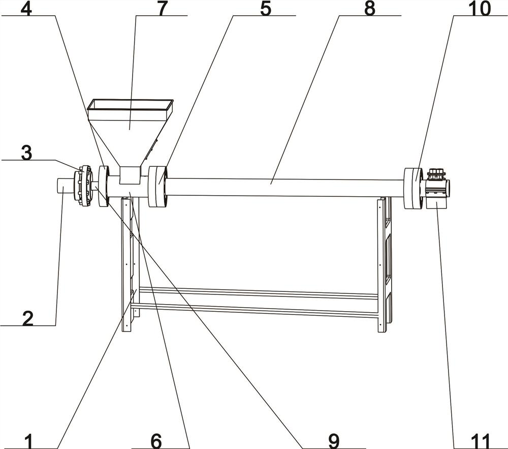
[0026]As shown in the figure, a micro-fit gap screw of a plastic film extruder includes a bracket 1, a power drive shaft 2, and a coupling 3; the bracket 1 is fixed at the bottom of the screw barrel 8, and the bracket 1 is used for Support the lower barrel 6 and screw barrel 8; the power drive shaft 2 is fixedly arranged on the left side of the coupling 3, the left end of the power drive shaft 2 is fixedly connected with the power output shaft of the reducer, and the right end of the power drive shaft 2 It is fixedly connected with the coupling 3; the first sealed shaft seat 4 is fixedly arranged at the left end position of the lower material barrel 6, and the second sealed shaft seat 5 is fixedly arranged at the right end position of the lower material barrel 6; the lower material bin 7 is fixed It is arranged at the up...


PUM


Abstract

The invention belongs to the technical field of extrusion of plastic films, and discloses a micro fit clearance screw rod of a plastic film extruder. A screw cylinder is in a hollow cylinder shape, the left end of the screw cylinder penetrates through the center of a second sealing shaft seat and is fixedly connected with the right end of a discharging barrel, and the right end of the screw cylinder penetrates through the center of a third sealing shaft seat and is fixedly connected with a die head; a screw rod is sleeved at the center of the screw cylinder, the left end of the screw rod extends to the right side of a coupler, the screw rod is fixedly connected with the center of the right side of the coupler, and the right end of the screw rod extends into the third sealing shaft seat; and the die head is fixedly arranged at the right end of the screw cylinder and communicates with the screw cylinder, and molten polypropylene material is extruded to form a thin film through the die head by utilizing the rotary conveying pressure of the screw rod. According to the micro fit clearance screw rod, the material conveying capability of the screw rod is improved, the retention time of the molten polypropylene material in the screw cylinder of the extruder is shortened, the extrusion efficiency of the extruder is improved, the power consumption is saved, and the phenomenon that molten polypropylene materials flow back in the screw cylinder is reduced.

Description

technical field [0001] The invention belongs to the technical field of plastic film extrusion, and in particular relates to a micro-fit gap screw of a plastic film extruder. Background technique [0002] The plastic film extruder is the necessary equipment for the pre-process in the process of producing container bags. It mainly feeds polypropylene particles into the screw barrel of the extruder through the lower hopper, and heats them to form molten polypropylene. At the same time, it uses the continuously rotating screw , the molten polypropylene is transported to the feeding end of the screw barrel, and the extrusion effect of the die is used to form a film, and finally it is cooled and shaped by a water tank and cut to form a flat yarn. The flat yarn is used as a textile yarn and spun into a cylinder by a circular loom Shaped container bag base fabric is used as the basic raw material for the production of container bags. [0003] In the prior art, polypropylene pellets...

Claims


Application Information

Patent Timeline
IPC IPC(8): B29C48/08B29C48/525B29C48/58B29C48/59
CPCB29C48/08B29C48/525B29C48/58B29C48/59
Inventor 周会杰郭少渠陈占国
Owner 洛阳市大资塑业有限公司
Features
  • Generate Ideas
  • Intellectual Property
  • Life Sciences
  • Materials
  • Tech Scout
  • Unparalleled Data Quality
  • Higher Quality Content
  • 60% Fewer Hallucinations
Learn More