Auxiliary indentation equipment for concrete construction pouring and rapid indentation method thereof

A concrete and indentation technology, applied in the field of concrete pouring, can solve the problems of inconvenient tamping and indentation of concrete

Active Publication Date: 2021-09-07
广东辰集建设工程有限公司
View PDF13 Cites 0 Cited by
  • Summary
  • Abstract
  • Description
  • Claims
  • Application Information

AI Technical Summary

Problems solved by technology

[0005] The purpose of the present invention is to provide an auxiliary indentation equipment for concrete construction and its rapid indentation method, which has the advantages of being convenient for tamping concrete and being convenient for indentation, and solves the problems that it is not convenient for tamping concrete and indentation

Method used


Image

  • Auxiliary indentation equipment for concrete construction pouring and rapid indentation method thereof
  • Auxiliary indentation equipment for concrete construction pouring and rapid indentation method thereof
  • Auxiliary indentation equipment for concrete construction pouring and rapid indentation method thereof

Examples


Embodiment 1

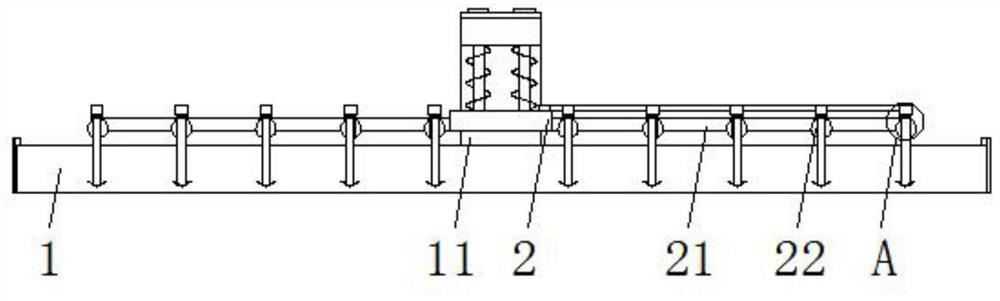
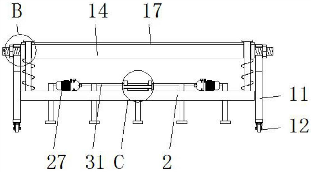
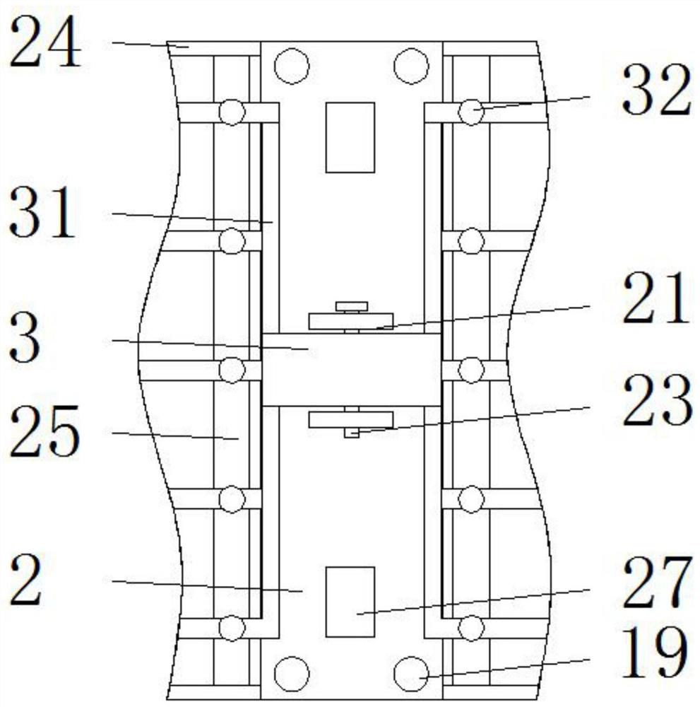
[0033]Embodiment 1: An auxiliary indentation equipment for concrete pouring and its rapid indentation method, including a mold body 1, a connecting plate 2, a block 3 and a fixing plate 14, and the outer walls of both sides of the mold body 1 are provided with support plates 11 , two support plates 11 are provided with a fixed plate 14 on the opposite side of the outer wall, a connecting plate 2 is arranged on one side of the outer wall of the lower end of the fixed plate 14, and connecting frames 24 are symmetrically installed on the outer walls of both sides of the connecting plate 2, and a connecting frame 24 is installed between the connecting frames 24. The indentation rods 25 distributed equidistantly in parallel, the indentation rods 25 are provided with through holes 26 equidistantly distributed in parallel, and a vibrating motor 27 is symmetrically installed on one side of the outer wall of the upper end of the connecting plate 2, as is well known to those skilled in th...

Embodiment 2

[0036] Embodiment 2: An auxiliary indentation equipment for concrete pouring and its rapid indentation method, including a mold body 1, a connecting plate 2, a block 3 and a fixing plate 14, and the outer walls of both sides of the mold body 1 are provided with support plates 11 , two support plates 11 are provided with a fixed plate 14 on the opposite side of the outer wall, a connecting plate 2 is arranged on one side of the outer wall of the lower end of the fixed plate 14, and connecting frames 24 are symmetrically installed on the outer walls of both sides of the connecting plate 2, and a connecting frame 24 is installed between the connecting frames 24. Indentation rods 25 distributed equidistantly and in parallel, inside the indentation rod 25 are provided with through holes 26 equidistantly distributed in parallel, a vibrating motor 27 is symmetrically installed on one side of the outer wall of the upper end of the connecting plate 2, and the outer wall of the connecting...


PUM


Abstract

The invention provides auxiliary indentation equipment for concrete construction pouring. The equipment comprises a mold body, a connecting plate, a clamping block and a fixing plate, supporting plates are arranged on the outer walls of the two sides of the mold body, the fixing plate is arranged on the outer walls of the opposite sides of the two supporting plates, a connecting plate is arranged on one side of the outer wall of the lower end of the fixing plate, connecting frames are symmetrically installed on the outer walls of the two sides of the connecting plate, indentation rods which are distributed in parallel at equal intervals are installed between the connecting frames, through holes which are distributed in parallel at equal intervals are formed in the indentation rods, vibration motors are symmetrically installed on one side of the outer wall of the upper end of the connecting plate, clamping sleeves are symmetrically mounted on the outer wall of the side, away from the vibration motors, of the connecting plate, and clamping blocks are arranged in the clamping sleeves. By arranging the indentation rods, the fixing plate and the connecting plate, the effect of conveniently indenting concrete is achieved, the workload of workers is reduced, the construction period is prevented from being affected, and the indentation making efficiency is improved.

Description

technical field [0001] The invention relates to the technical field of concrete pouring, in particular to an auxiliary indentation device for concrete pouring and a rapid indentation method thereof. Background technique [0002] Concrete is a general term for engineering composite materials in which aggregates are cemented into a whole by cementitious materials. Concrete is one of the most important civil engineering materials today. It is composed of cementitious materials, granular aggregates (also known as aggregates), water, and additives and admixtures added when necessary, prepared in a certain proportion, uniformly stirred, densely formed, cured and hardened. A kind of artificial stone. Concrete pouring refers to the process of pouring concrete into the mold until it is plasticized. In civil engineering, concrete and other materials are put into the mold to make a predetermined shape. When pouring concrete, the free height of concrete should not exceed 2m. Correspon...

Claims


Application Information

Patent Timeline
Patent Type & Authority Applications(China)
IPC IPC(8): E01C19/38E01C19/43
CPCE01C19/38E01C19/43Y02W30/91
Inventor 李伟中黄科成刘文斌刘锦钏
Owner 广东辰集建设工程有限公司
Why Eureka
Try Eureka