Conveying hose system for salt field

A technology for conveying hoses and salt fields. It is used in pipeline systems, hoses, hose connection devices, etc., and can solve the problems of hard pipes being difficult to bend, hard pipe joints being corroded, and labor intensive.

Pending Publication Date: 2021-09-07
JIANGSU ASOE NEW MATERIAL TECH
View PDF0 Cites 0 Cited by
  • Summary
  • Abstract
  • Description
  • Claims
  • Application Information

AI Technical Summary

Problems solved by technology

[0003] When the tractor turns, the hard pipe used for transportation is not easy to bend, and the hose connected to the front-end salt pumping machine is easy to bend, and...

Method used


Image

  • Conveying hose system for salt field
  • Conveying hose system for salt field
  • Conveying hose system for salt field

Examples


Embodiment Construction

[0033] The following describes several preferred embodiments of the present invention with reference to the accompanying drawings, so as to make the technical content clearer and easier to understand. The present invention can be embodied in many different forms of embodiments, and the protection scope of the present invention is not limited to the embodiments mentioned herein.

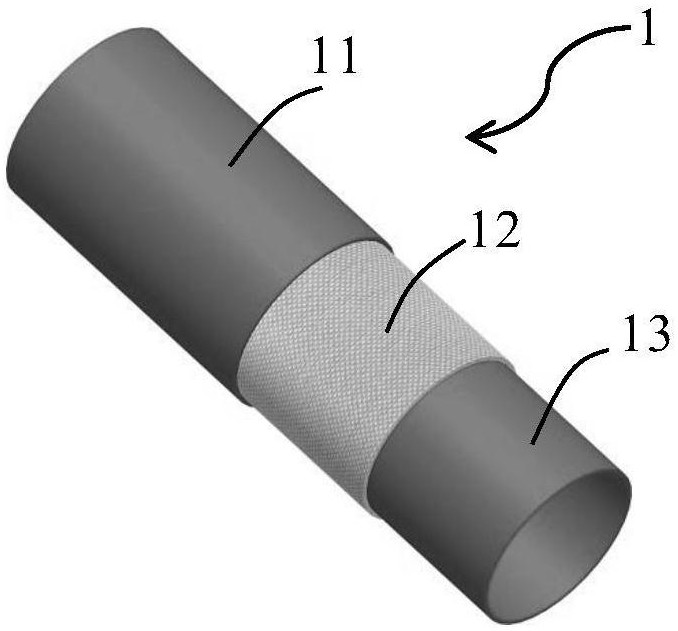
[0034] Such as figure 1 As shown, unlike the PE hard pipe in the prior art, the present invention uses a polyurethane material hose. In a preferred embodiment, this polyurethane hose 1 includes a three-layer structure: a polyurethane inner layer 1, a polyester braided reinforced middle Layer 2 and polyurethane outer layer.

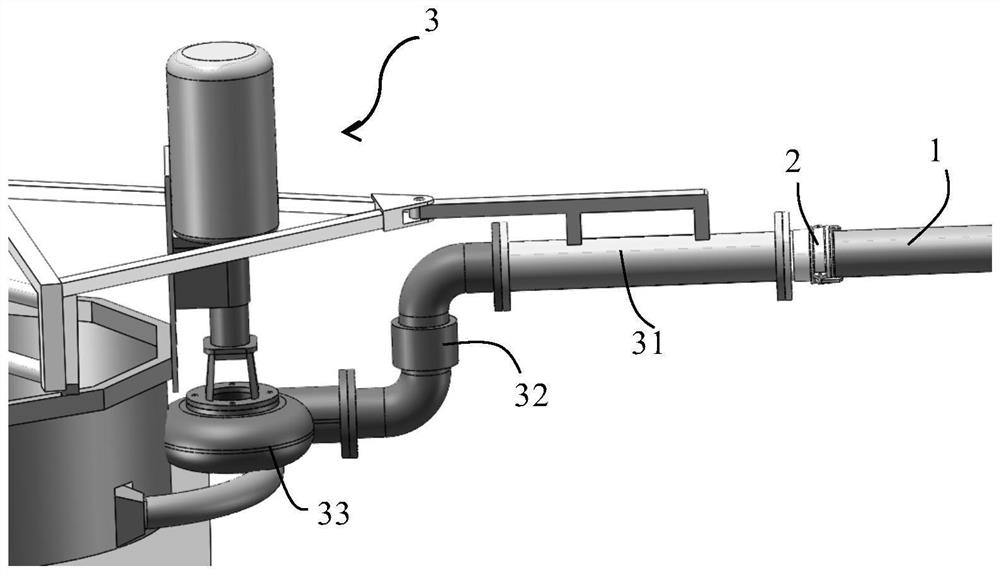
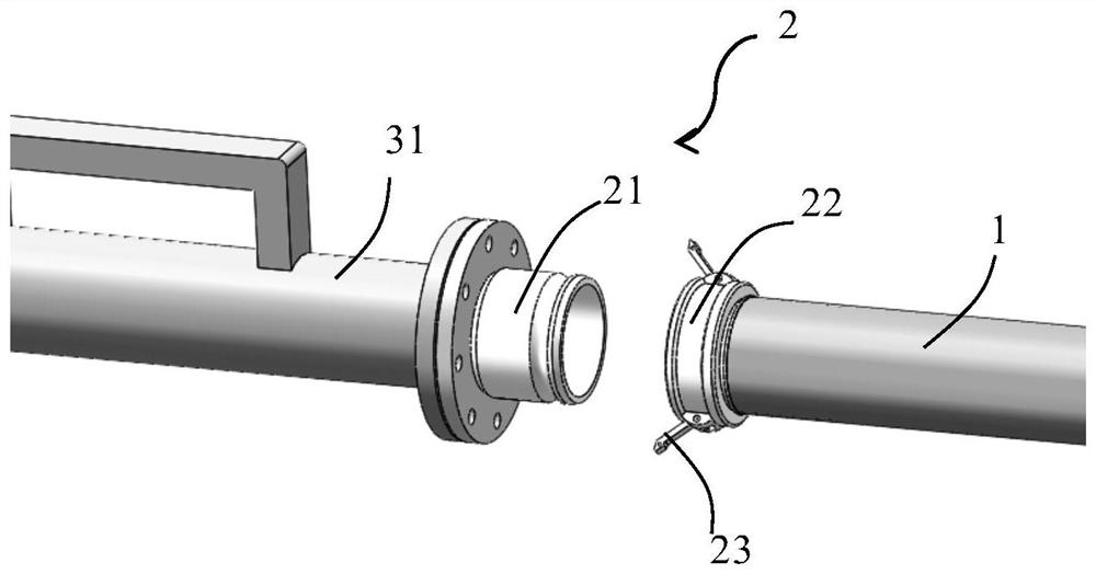
[0035] The connection between the hose 1 and the salt collecting truck 3 is as follows: figure 2 As shown, the pump 33 on the salt collection truck 3 is connected to the transition pipe 31 through the slewing bearing 32 , and the transition pipe 31 is connected to the hose 1 th...


PUM


Abstract

The invention discloses a conveying hose system for a salt field. Conveying hoses are polyurethane hoses and are connected with a salt collecting vehicle, a pump on the salt collecting vehicle is connected with a transition pipe through a slewing bearing, the transition pipe is connected with the conveying hoses through a quick connector, and the two conveying hoses are also connected through a quick connector.

Description

technical field [0001] The invention relates to a conveying hose system, in particular to a conveying hose system used in a salt field. Background technique [0002] At present, when domestic salt farms collect and transport crystallized salt from salt ponds, the commonly used operation method is to fix the centrifugal pump behind the tractor and use hard PE pipes for transportation. The hard pipes are about 9 meters long and adjacent to each other. The rigid pipes are connected by carbon steel seamless pipes and fixed with clamps. [0003] When the tractor turns, the hard pipe used for transportation is not easy to bend, and the hose connected to the front-end salt pumping machine is easy to bend, and it is easy to get caught when turning, which is not conducive to salt transportation; Short, troublesome installation, disassembly and transfer, high labor intensity and more labor. Contents of the invention [0004] In view of the above-mentioned defects of the prior art,...

Claims


Application Information

Patent Timeline
IPC IPC(8): F16L33/02F16L3/02F16L11/133F16L55/00F16L58/18F16L57/06F16L27/08F17D1/08
CPCF16L33/02F16L3/02F16L11/133F16L55/00F16L58/18F16L57/06F16L27/08F17D1/08
Inventor 倪厚明石克兵郭忠谋邹华山
Owner JIANGSU ASOE NEW MATERIAL TECH
Why Eureka
Try Eureka