Lifting stand column device

A lifting column and accommodating cavity technology, applied in the installation of electromechanical devices, transmission devices, cables, etc., can solve the problems of slow lifting speed, small number of cables, and small eccentric load moment.

Pending Publication Date: 2021-09-07
上海追术科技有限公司
View PDF0 Cites 2 Cited by
  • Summary
  • Abstract
  • Description
  • Claims
  • Application Information

AI Technical Summary

Problems solved by technology

However, the traditional lifting column mostly adopts a built-in motor scheme, and the internal wiring is mostly a spiral line. Due to the limitation of the internal space of the device, the number of internal cables is small, which cannot meet some usage scenarios that require a large number of internal wiring; the lifting speed is slow , and the speed i

Method used


Image

  • Lifting stand column device
  • Lifting stand column device
  • Lifting stand column device

Examples


Embodiment

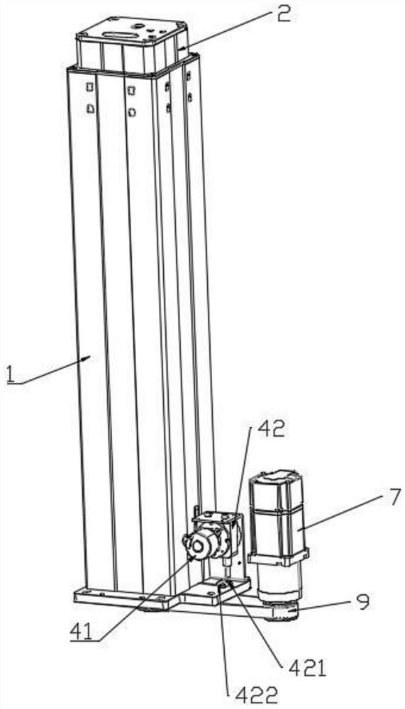
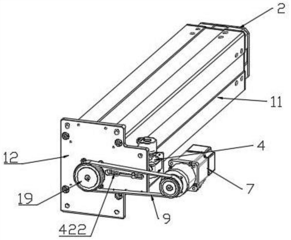
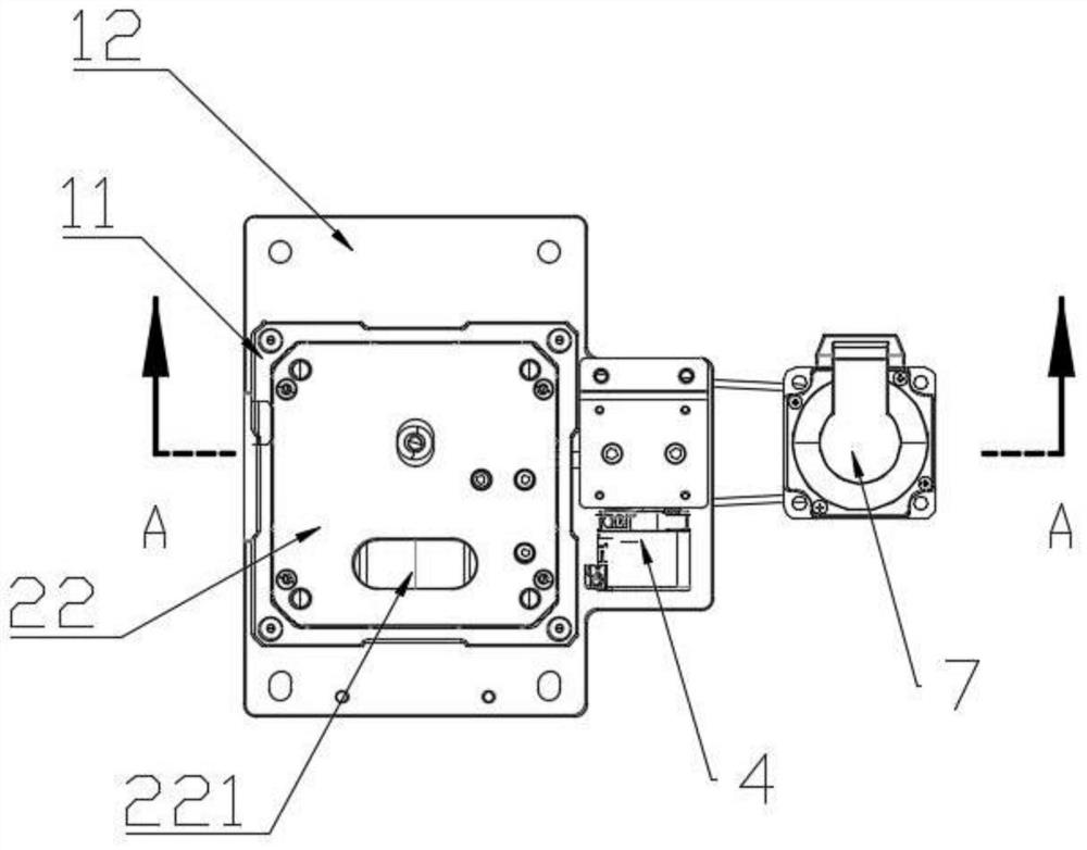
[0040] see Figure 1 to Figure 13 , figure 1 A schematic diagram of the three-dimensional structure of the lifting column device provided in the embodiment of the present application at an angle; figure 2 A schematic diagram of the three-dimensional structure of the lifting column device provided in the embodiment of the present application at another angle; image 3 for figure 1 A schematic top view of the lifting column device shown; Figure 4 for image 3 The schematic cross-sectional structure at A; Figure 5 A partial structural schematic diagram of the outer cylinder provided in the embodiment of the present application; Figure 6 Schematic diagram of the structure of the lifting column device provided in the embodiment of the present application when the outer cylinder wall is removed; Figure 7 for Figure 6 The schematic diagram of the structure of the lifting column device at an angle when the inner cylinder wall is further removed; Figure 8 for Figure 6 ...


PUM


Abstract

The invention discloses a lifting stand column device. The lifting stand column device comprises an outer cylinder, an inner cylinder, a drag chain and a position feedback device, a first containing cavity is formed in the outer cylinder, an opening is formed in one end of the outer cylinder in the axis direction, the opening communicates with the first containing cavity, and the inner cylinder and the drag chain are located in the first containing cavity separately. The inner cylinder and the outer cylinder are the same in axial direction, the inner cylinder can be driven to move in the outer cylinder in the axis direction of the outer cylinder, one end of the drag chain is connected with the outer cylinder, the other end of the drag chain is connected with the inner cylinder, and the position feedback device is configured to feed back the position of the inner cylinder in the outer cylinder. According to the lifting stand column device, work is stable, the number of wires capable of being arranged in the lifting stand column device is large, the lifting speed is high and adjustable, the unbalance loading capacity is large, the lifting position can be accurately positioned, and by additionally arranging a spring gap eliminating device, a transmission gap generated when a trapezoidal lead screw rotates forwards and backwards can be effectively eliminated.

Description

technical field [0001] The invention relates to the technical field of medical equipment, in particular to a lifting column device for medical equipment. Background technique [0002] Lifting columns are common components in medical equipment. For example, during surgery, doctors need to adjust the height of the operating table according to their own height and the condition of the patient to facilitate the operation. However, the traditional lifting column mostly adopts a built-in motor scheme, and the internal wiring is mostly a spiral line. Due to the limitation of the internal space of the device, the number of internal cables is small, which cannot meet some usage scenarios that require a large number of internal wiring; the lifting speed is slow , and the speed is not adjustable, most of them are constant speed; the eccentric load moment is small; the position feedback is inaccurate, most of them have no position feedback, or the encoder behind the motor records the po...

Claims


Application Information

Patent Timeline
IPC IPC(8): F16M11/26F16G13/16F16H25/20F16H25/24H02G11/00H02K7/10A61G13/10A61G13/06
CPCF16M11/26F16G13/16F16H25/2015F16H25/2003F16H25/24F16H25/2454H02G11/00H02K7/1004A61G13/10A61G13/06F16H2025/2081F16H2025/2096F16H2025/204
Inventor 不公告发明人
Owner 上海追术科技有限公司
Why Eureka
Try Eureka