Check patentability & draft patents in minutes with Patsnap Eureka AI!

Reflection structure, particle measuring device comprising same and detection method of particle measuring device

A reflective structure and measurement device technology, which is applied in the direction of measurement devices, particle size analysis, particle and sedimentation analysis, etc., can solve the problems of high processing complexity, difficult mask plate structure design, and inability to realize backscattered light detection

Pending Publication Date: 2021-09-07
上海纬冉科技有限公司
View PDF0 Cites 0 Cited by
  • Summary
  • Abstract
  • Description
  • Claims
  • Application Information

AI Technical Summary

Problems solved by technology

[0004] (1) The reflection of the shading device or the light-blocking area of ​​the mask and the influence of scattered light are easy to introduce stray light into the optical system in the measurement device, thereby affecting the signal-to-noise ratio of the entire measurement device, and this method can only achieve forward The detection of scattered light, the detection of backscattered light cannot be realized
[0005] (2) The form of the shading device or the mask plate can not adjust the optical path in real time and online with the help of direct light
[0006] (3) The structural design of the mask plate is difficult and the processing complexity is high

Method used


Image

  • Reflection structure, particle measuring device comprising same and detection method of particle measuring device
  • Reflection structure, particle measuring device comprising same and detection method of particle measuring device
  • Reflection structure, particle measuring device comprising same and detection method of particle measuring device

Examples


Embodiment 1

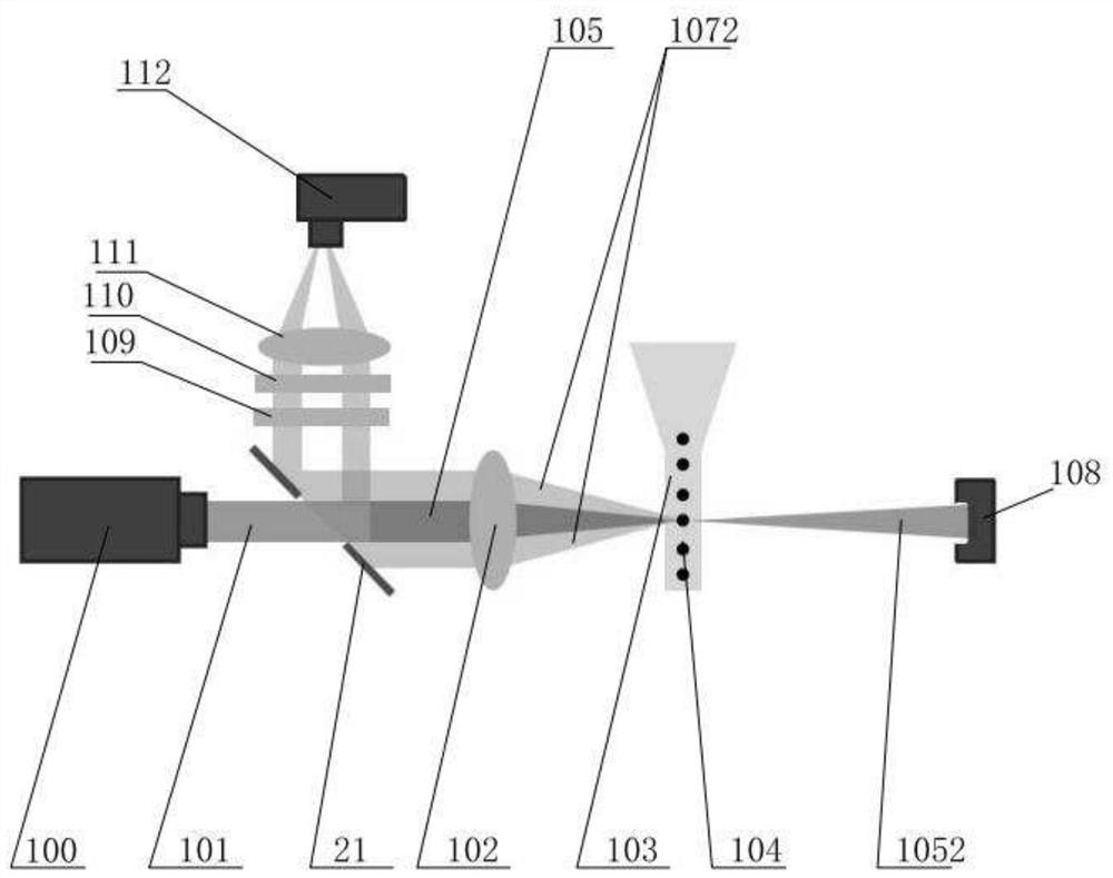
[0055] Please refer to figure 1, a particle measurement device, comprising a light source 100, a reflective structure 20, at least one first lens 102, a flow chamber 103, a detector 112 and a blocking element 108, wherein the light source 100 is used to emit an illumination beam; the first lens 102 is used to focus the illumination beam to the center of the flow chamber 103; the flow chamber 103 is used to make the liquid droplets containing particles sequentially irradiated by the illumination beam and generate direct light and at least one scattered light; the The reflective structure 20 is used to separate the direct light and at least one of the scattered light; the detector 112 is used to receive and detect at least one of the scattered light; the shielding element 108 is used to block and / or eliminate the direct light.

[0056] Specifically, please refer to figure 1 When the incident direction of the illumination light beam is the same as the outgoing direction of the ...

Embodiment 2

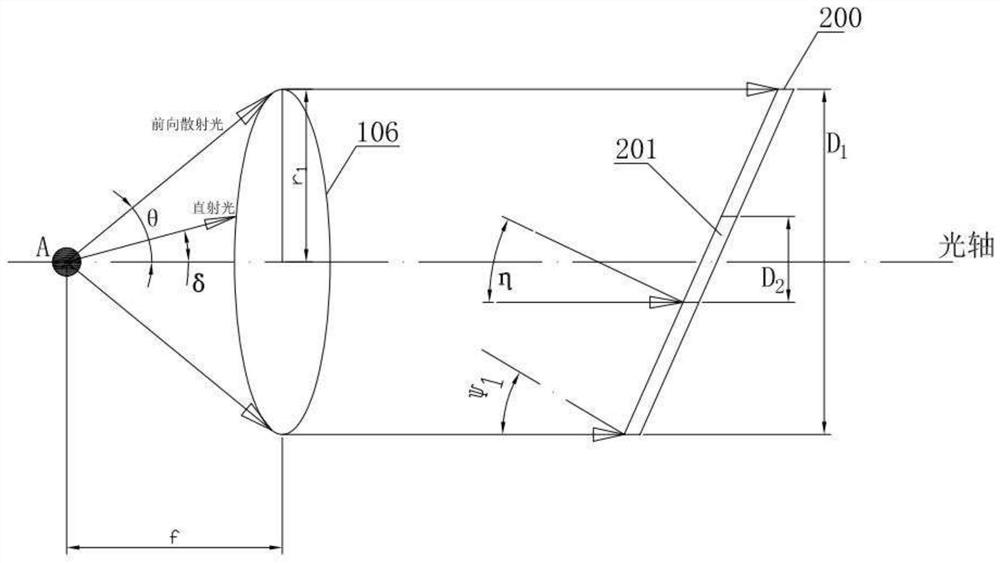
[0101] The structure and detection method of the second embodiment are mostly the same as those of the first embodiment, except that the backscattered light signal 1072 is used to characterize the number and size information of the particles. In the second embodiment, the propagation direction of the backscattered light signal 1072 is The propagation directions of the incident light beam 101 and the outgoing second outgoing direct light 1052 are opposite to each other, so mutual interference between the incident light beam 101 and the backscattered light signal 1072 needs to be avoided. Due to the different propagation directions, the reflective structure 20 is disposed between the flow chamber 103 and the light source 100 , and the reflective surface of the reflective structure 20 may face the propagation direction of the backscattered light signal 1072 .

[0102] Further, please continue to refer to figure 2 with Figure 4 , in the particle detection device described in th...


PUM

PropertyMeasurementUnit
Caliberaaaaaaaaaa
Caliberaaaaaaaaaa
Caliberaaaaaaaaaa

Abstract

The invention relates to a reflection structure, a particle measuring device comprising the same and a detection method of the particle measuring device, the reflection structure comprises a mirror body and a hole formed in the mirror body, and the mirror body is provided with a reflection surface used for reflecting a scattered light signal; the hole is used for transmitting emergent direct light, and the center of the hole is coaxial with the optical axis of the emergent direct light. According to the invention, the reflection structure is added to separate the direct light signal and the scattered light signal generated by the particles by the illumination light beam, and the direct light signal is dredged to the position far away from the measurement point of a flow chamber, so that the scattered light can be received and detected while the direct light is eliminated; the stray light problem caused by the adoption of a shading rod or a mask plate is avoided, and the signal-to-noise ratio in the measurement process is further improved.

Description

technical field [0001] The invention relates to the technical field of optical equipment, in particular to a reflection structure, a particle measuring device including the structure and a detection method thereof. Background technique [0002] The particle measurement device is used to evaluate the size, quantity, material and other properties of the sample. It mainly introduces the sample particles into the fluid, and then illuminates the fluid with an illuminating beam. When the illuminating beam enters the fluid, it interacts with the sample, causing the light to flow from all directions Scattering produces scattered light. Due to the change of sample particle size or material, the scattered light scattered in different directions will also change accordingly. According to different measurement requirements, different measurement forms are used to collect and detect the scattered light. , while avoiding direct light from interfering with scattered light signals. [0003...

Claims


Application Information

Patent Timeline
IPC IPC(8): G01N15/02
CPCG01N15/0211
Inventor 宋卓
Owner 上海纬冉科技有限公司
Features
  • R&D
  • Intellectual Property
  • Life Sciences
  • Materials
  • Tech Scout
  • Unparalleled Data Quality
  • Higher Quality Content
  • 60% Fewer Hallucinations
Learn More