Camera lens, camera shooting device and electronic equipment

A camera device and lens technology, applied in the field of photography, can solve the problems of high surface reflectivity, stray light, etc.

Inactive Publication Date: 2021-09-07
JIANGXI JINGCHAO OPTICAL CO LTD
View PDF0 Cites 0 Cited by
  • Summary
  • Abstract
  • Description
  • Claims
  • Application Information

AI Technical Summary

Problems solved by technology

[0003] In related technologies, glue is placed at the contact position between the lens and the lens barrel, and then directly cured. After the glue is cured, the surface is smooth, and the light is directly reflected to the imaging surface after contacting the surface of the glue. Although the glue is black after curing, the surface reflection The rate is still high, and it is transparent in the thinner part of the glue layer. The light may pass through the glue or be strongly reflected on the surface, resulting in serious stray light.

Method used


Image

  • Camera lens, camera shooting device and electronic equipment
  • Camera lens, camera shooting device and electronic equipment

Examples


Embodiment Construction

[0027] Embodiments of the present invention are described in detail below, and the embodiments described with reference to the drawings are exemplary, and embodiments of the present invention are described in detail below.

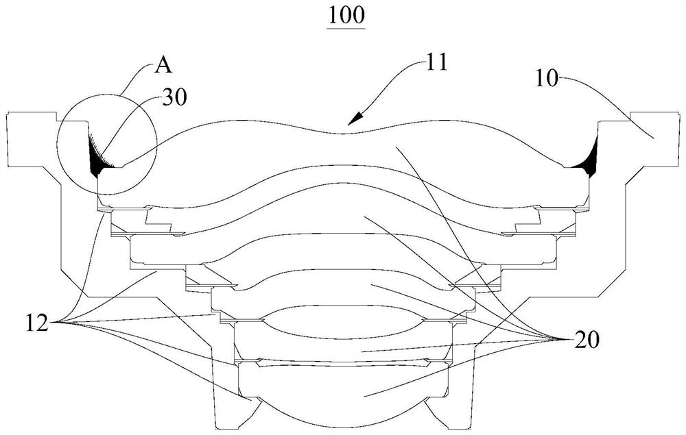
[0028] Refer below Figure 1-Figure 2 The lens 100 according to the embodiment of the present invention will be described in detail.

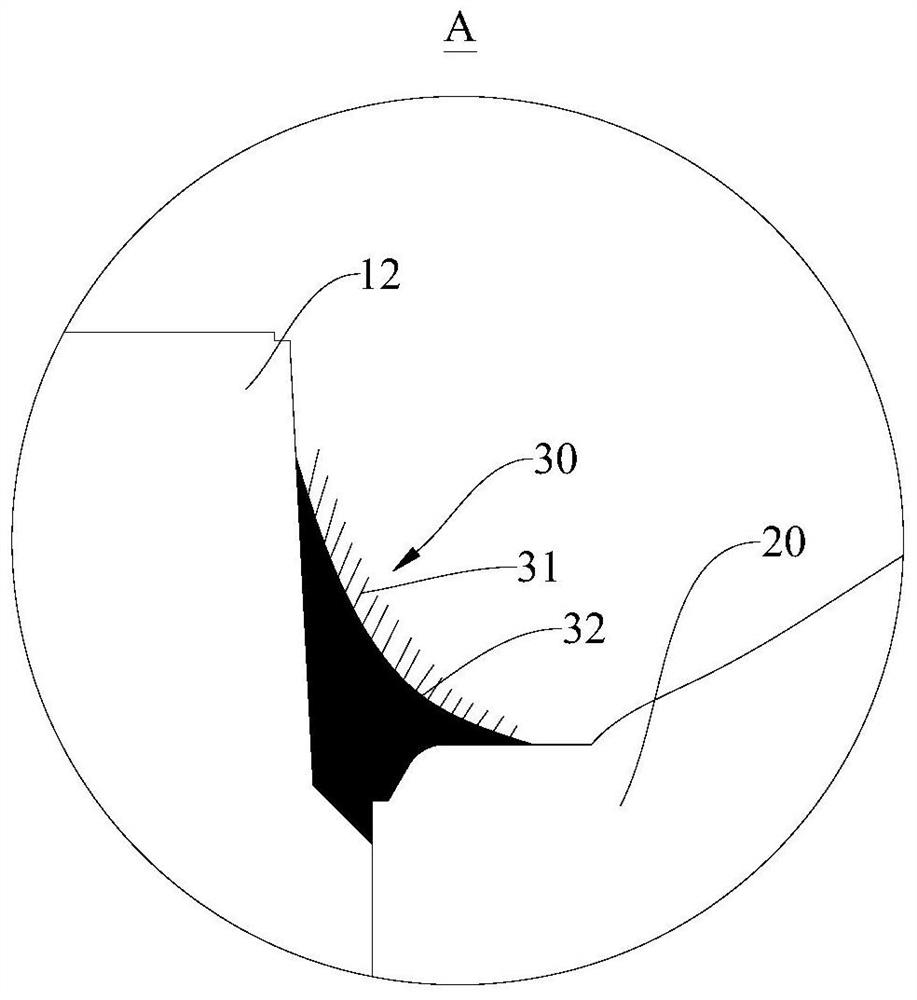
[0029] Such as figure 1 As shown, the lens 100 of the embodiment of the present invention includes: a lens barrel 10, a lens 20, glue 32 and ceramic powder, the inside of the lens barrel 10 is formed as an installation cavity 11, the lens 20 is installed in the installation cavity 11, and the glue 32 is coated on the Between the lens barrel 10 and the lens 20 , the lens 20 can be fixed on the lens barrel 10 through the glue 32 , and the ceramic powder is arranged in the glue 32 before the glue 32 is cured. Wherein, the setting method of the ceramic powder can be spraying.

[0030] Therefore, by spraying ceramic powder on...


PUM


Abstract

The invention discloses acamera lens, which comprises a lens barrel, a lens, glue and ceramic powder, wherein an installation cavity is formed in the lens barrel, the lens is installed in the installation cavity, the glue is coated between the lens barrel and the lens, and the ceramic powder is arranged in the glue before the glue is solidified. The ceramic powder is sprayed on the surface of the glue, so that the surface of the glue is uneven, light rays are scattered on the surface of the glue, the extinction effect is achieved, needle head blocking can be reduced, and the glue dispensing process is stable. In addition, the ceramic powder is easy to obtain and low in processing cost.

Description

technical field [0001] The invention relates to the field of imaging, in particular to a lens, an imaging device and electronic equipment. Background technique [0002] In recent years, as users pay more and more attention to the reflection of lens stray light and the reliability of the lens, reducing stray light and improving lens reliability have gradually become the focus of design. [0003] In related technologies, glue is placed at the contact position between the lens and the lens barrel, and then directly cured. After the glue is cured, the surface is smooth, and the light is directly reflected to the imaging surface after contacting the surface of the glue. Although the glue is black after curing, the surface reflection The rate is still high, and it is transparent at the thinner part of the glue layer. The light may pass through the glue or be strongly reflected on the surface, resulting in serious stray light. Contents of the invention [0004] The present inven...

Claims


Application Information

Patent Timeline
Patent Type & Authority Applications(China)
IPC IPC(8): G02B7/02G03B30/00
CPCG02B7/021G02B7/025
Inventor 胡德忠吴俊甫邹海荣
Owner JIANGXI JINGCHAO OPTICAL CO LTD
Why Eureka
Try Eureka