An electric vehicle wiring harness automatic pipe threading equipment

An automatic threading, electric vehicle technology, applied in cable laying equipment, mechanical equipment, engine components, etc., can solve the problems of reducing the efficiency of wire harness threading, inability to align the center line, and failure of harness threading, etc. Pipe efficiency, reduce pipe penetration errors, and reduce the effect of wire harness pipe penetration errors

Active Publication Date: 2022-03-11
徐州博虎电动车科技有限公司
View PDF4 Cites 1 Cited by
  • Summary
  • Abstract
  • Description
  • Claims
  • Application Information

AI Technical Summary

Problems solved by technology

[0005] In order to make up for the deficiencies of the existing technology, to solve the problem that the wire harness and the center line of the sleeve cannot be completely aligned and coincident when the wire harness is pushed into the sleeve by the pay-off unit, which may easily cause the wire harness to scratch the inner wall of the sleeve, or even appear In case of wire harness threading failure, the problem of reducing the efficiency of wire harness threading, the invention proposes an electric vehicle wire harness automatic threading device

Method used


Image

  • An electric vehicle wiring harness automatic pipe threading equipment
  • An electric vehicle wiring harness automatic pipe threading equipment
  • An electric vehicle wiring harness automatic pipe threading equipment

Examples


Embodiment 1

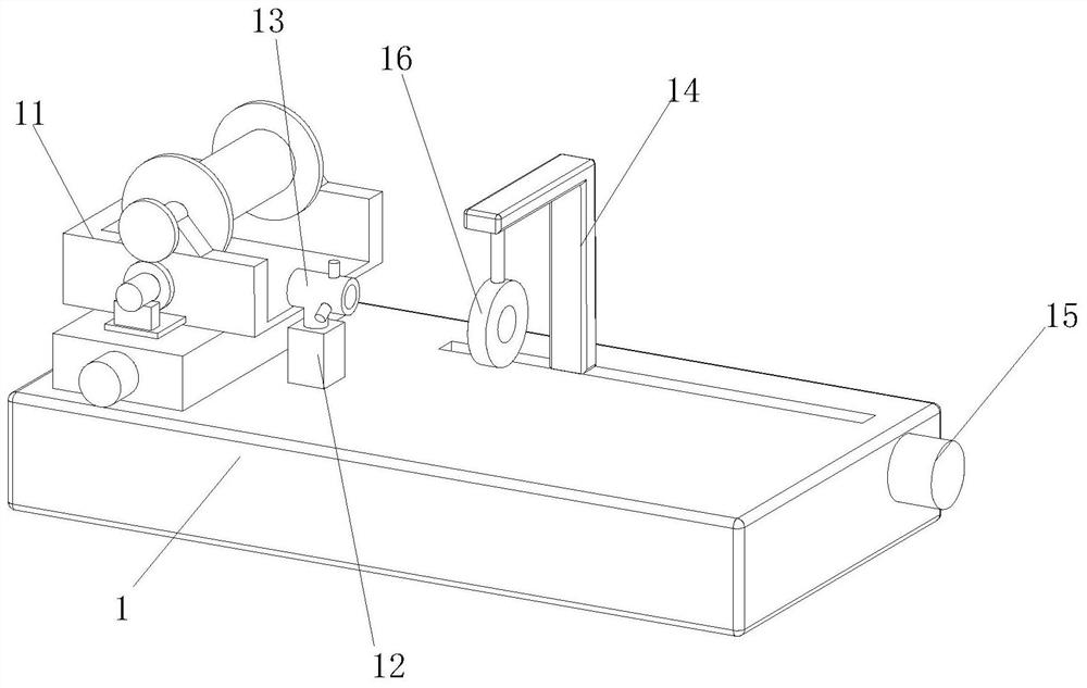
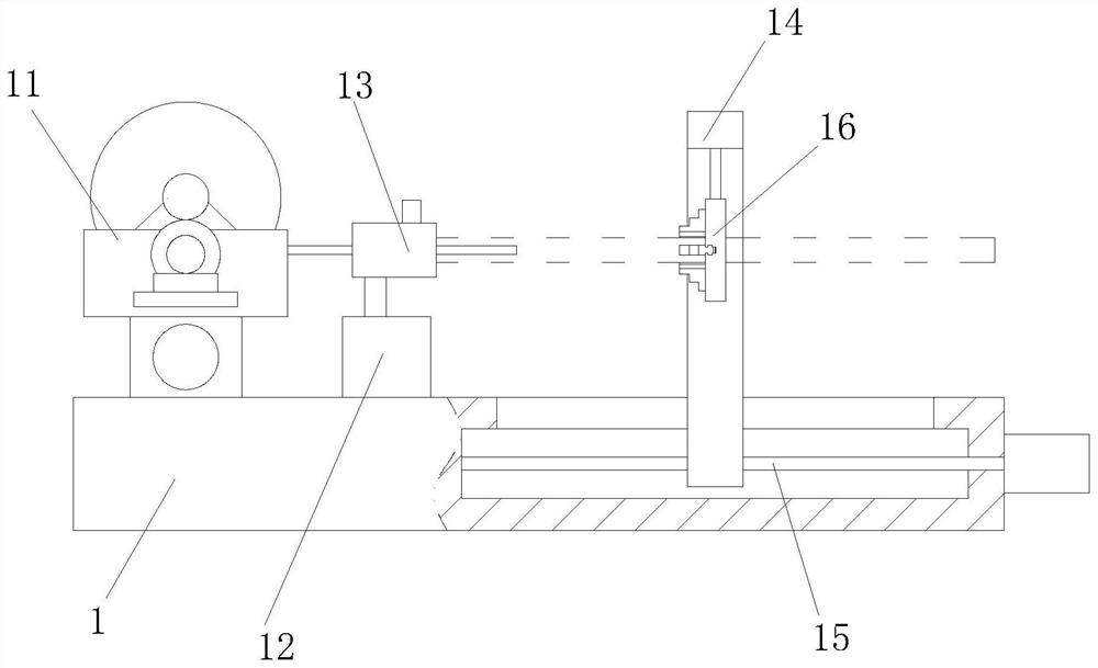
[0032] Such as Figure 1 to 6 As shown, an electric vehicle wire beam automatic tube device according to the present invention includes a table 1; the top end of the table 1 is provided with an amplifier unit 11 and a fixing seat 12; the fixing seat 12 is located at a disposing unit. 11 placement side; the top end of the fixing seat 12 is provided with a wire barrel 13 by a fixed column; the working unit 1 is connected to the L-shaped plate 14 through the moving unit 15, and the L-shaped plate 14 is away from the end portion of the workbench 1. The bottom end is solid to have a trip chuck 16 by a fixed column; the centerline of the trunculating chuck 16 and the centerline of the wire barrel 13 is coincidentically; and there are three hydraulic cylinders 17, and there are three hydraulic cylinders 17, and hydraulic cylinders. 17 The hydraulic rod 18 set in the lead barrel 13, points to the center point of the lead barrel 13; when operating, in the prior art, the discharge unit 11 pu...

Embodiment 2

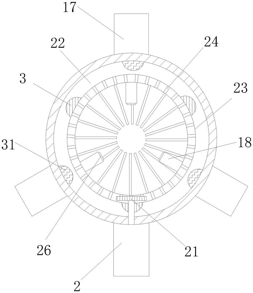
[0041] See Figure 7 - Figure 8 As shown, Comparative Example 1, as another embodiment of the present invention, the first arc-shaped block 3 is hollow, and the first arc-shaped block 3 is opened between the outer wall of the annular plate 23. Cavity 6; the first ring groove 22 slot bottom is fixed to a magnetic block 63 relative to the first arc block 3; the inner wall of the first cavity 6 is fixed to the first magnetic ball 62 through the elastic rope 61 The first magnetic ball 62 and the magnetic block 63 are mutually rejected; when the annular plate 23 is rotated at the first annular groove 22, the first magnetic ball 62 moves outward in the spring elastic force in the first arc. When the block 3 and the magnetic block 63 are approached, the first magnetic ball 62 and the magnetic block 63 are urgently pushed into the inner wall of the first cavity 6, and the outer side wall of the vibration ring plate 23 is driven. The plate 23 is clearly sweeping brush, which not only achiev...


PUM


Abstract

The invention belongs to the technical field of electromechanical technology for electric vehicles, and specifically relates to an automatic wire harness threading equipment for electric vehicles, including a workbench; The line unit is on the side where the wire is released; the top of the fixed seat is provided with a wire barrel through the fixed column; the L-shaped plate is connected to the workbench through the mobile unit, and the bottom end of the L-shaped plate away from the workbench is fixed through the fixed column. Connected with a three-jaw chuck; the invention provides an automatic wire harness threading device for an electric vehicle to solve the problem that when the wire harness is pushed into the sleeve by the pay-off unit, the centerlines of the wire harness and the sleeve cannot be completely aligned and overlapped, which may easily cause the wire harness to pass through the sleeve. The wire harness scratches the inner wall of the casing, and even the wire harness fails to pass through the pipe, which reduces the efficiency of the wire harness through the pipe.

Description

Technical field [0001] The present invention belongs to the technical field of electric vehicle electromechanical technology, and is specifically a driving pipe for automatic wire harness. Background technique [0002] In the electric vehicle electronic device, the electronic wire harness is required, and the electron harness refers to a contact terminal (connector) which is impulsive from the copper, and then plastic pressure insulator or external metal housing is plasticized. The components of the connecting circuit are bundled with the wire harness to prevent the electronic wire harness from being damaged, and the harness is usually required to protect the wire harness to protect the electronic harness. [0003] There have also been some technical solutions for electric vehicle electronic mechanical technology, such as the application number 20,2010,561332 discloses a pipeline for electronic wire beam processing, including a table, a disposing device, a positioning device. , T...

Claims


Application Information

Patent Timeline
Patent Type & Authority Patents(China)
IPC IPC(8): H02G1/08F16N11/08B08B1/04B08B1/02
CPCH02G1/08F16N11/08B08B1/04B08B1/002B08B1/02
Inventor 周威威
Owner 徐州博虎电动车科技有限公司
Why Eureka
Try Eureka