Eureka AIR delivers breakthrough ideas for toughest innovation challenges, trusted by R&D personnel around the world.

Electric power generation cycle application storage system

A storage system and electric power technology, applied in the direction of battery circuit devices, current collectors, electromechanical devices, etc., can solve problems such as current consumption, damage to generator components, and generator failure to operate normally

Pending Publication Date: 2021-09-07
LINENG TECH CORP
View PDF0 Cites 0 Cited by
  • Summary
  • Abstract
  • Description
  • Claims
  • Application Information

AI Technical Summary

Problems solved by technology

[0003] Due to the limited efficiency of existing generators in converting kinetic energy into electrical energy, usually when a transmission device is paired with a generator, the generated electrical energy is also limited. Therefore, the electrical energy generated by the generator is supplied back to the transmission When the transmission device provides power to the generator to generate electricity in a cycle, the generator cannot achieve the purpose of cycle power generation and power output due to the loss generated by the transmission device and the generator during operation.
[0004] In addition, during the conduction process, due to the magnetic resistance included in the coil itself, the current will be lost (for example: copper loss and iron loss), thereby generating heat energy, which will damage the internal components of the generator and cause power generation. The machine does not have a normal operation. Therefore, how to use one transmission device with multiple generators to generate multiple electric power, and store and recycle the electric power, while reducing the loss generated during the operation of the generator, and reducing the generation of heat energy is a must. an important subject

Method used


Image

  • Electric power generation cycle application storage system
  • Electric power generation cycle application storage system
  • Electric power generation cycle application storage system

Examples


Embodiment Construction

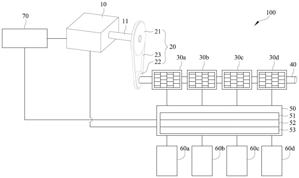
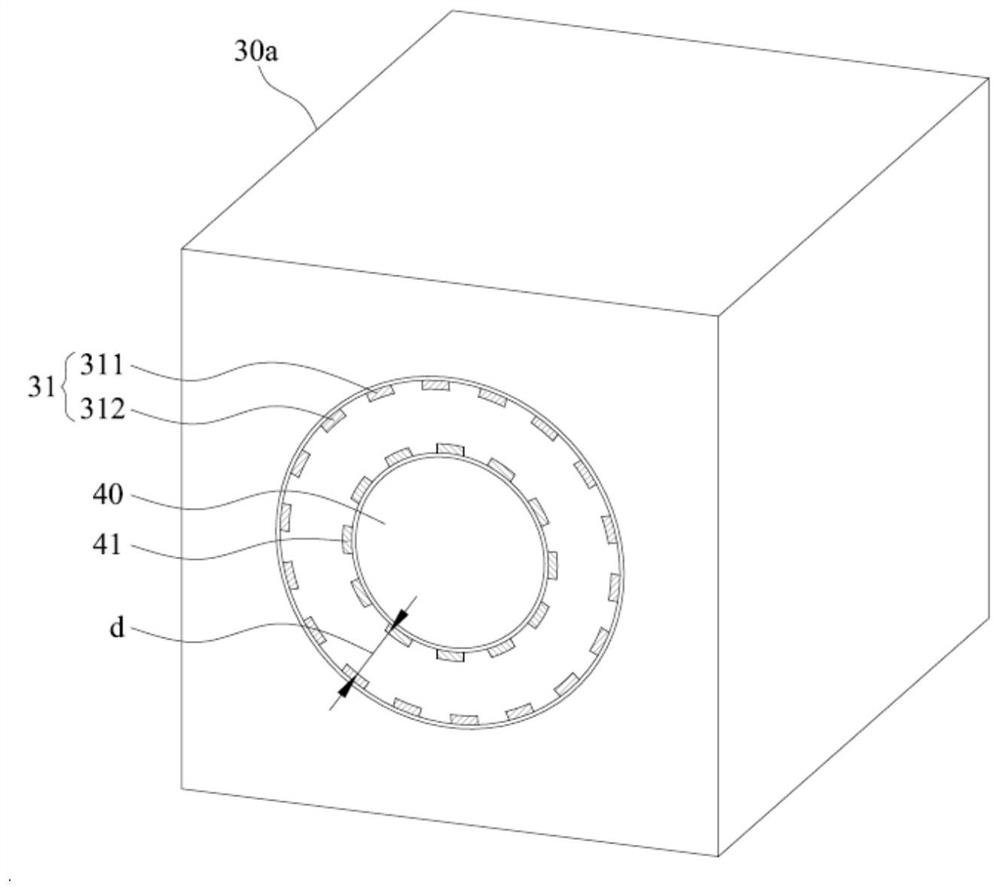
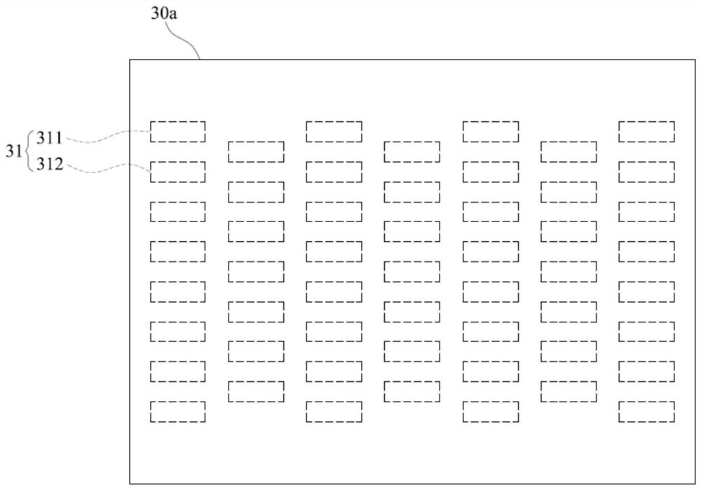
[0025] see Figure 1 to Figure 4 as shown, figure 1 It is a perspective view of the first embodiment of the present invention, figure 2 is a perspective view of the power generation module of the first embodiment of the present invention, image 3 It is a schematic diagram of the stator arrangement in the power generation module of the first embodiment of the present invention, Figure 4 It is a schematic diagram of the arrangement of power generation modules according to the first embodiment of the present invention. An embodiment of the present invention provides a power generation cycle application storage system 100, including:

[0026] A driving module 10 , the driving module 10 includes a rotating shaft 11 , and the rotating shaft 11 rotates relative to the driving module 10 . In this example, if figure 1 As shown, the driving module 10 is a driving motor, and the rotating shaft 11 is a driving shaft of the driving motor.

[0027] A speed change module 20 , one en...


PUM


Abstract

The invention provides an electric power generation cycle application storage system, which comprises a driving module, a speed change module, multiple power generation modules, a control module and a power supply piece, wherein the power generation modules are connected in series through a rod body, the control module is electrically connected with the plurality of power modules, the power supply piece is electrically connected with the driving module, the power supply piece is electrically connected with the control module, multiple stator assemblies are arranged in the power generation module, multiple rotor assemblies are arranged on the circumferential wall of the rod body, the stator assemblies are arranged in a staggered surrounding mode, the rotor assemblies correspond to the stator assemblies, the power generation module provides power for the control module, and the control module provides power for the power module and the power supply piece. Therefore, the driving module rotates the rod body through the speed change module, the rod body rotates the multiple power generation modules at the same time, so that multiple pieces of electric power are generated, and then the electric power is used for charging the power supply piece and providing the electric power to the electric power module through the control module.

Description

technical field [0001] The invention relates to an electric power generation storage system, in particular to an electric power generation cycle application storage system. Background technique [0002] In today's society, generators are ubiquitous. Multiple magnetic generators use the transmission device to supply power to the generator, and the kinetic energy is converted into electrical energy through the generator. Furthermore, the generator includes a stator structure and a rotor structure. In the process of converting into electrical energy, the current will be conducted in the stator winding, and the current magnetic effect will be generated. [0003] Due to the limited efficiency of existing generators in converting kinetic energy into electrical energy, usually when a transmission device is paired with a generator, the generated electrical energy is also limited. Therefore, the electrical energy generated by the generator is supplied back to the transmission When t...

Claims


Application Information

Patent Timeline
IPC IPC(8): H02K7/18H02K16/00H02J7/14
CPCH02K7/1807H02K16/00H02J7/1423
Inventor 李志郁
Owner LINENG TECH CORP
Why Eureka
Eureka Blog
Learn More