Forming method of block stator, block stator and motor under full-scale control

A full-size, stator technology, applied in the manufacture of stator/rotor bodies, manufacturing tools, electric components, etc., can solve the problems of motor stator and rotor iron cores that cannot be aligned, and achieve the effects of saving the number of tooling, reliable forming, and easy switching of tooling

Active Publication Date: 2022-07-22
WUHAN HUADA NEW TYPE MOTOR CO LTD
View PDF7 Cites 0 Cited by
  • Summary
  • Abstract
  • Description
  • Claims
  • Application Information

AI Technical Summary

Problems solved by technology

The perpendicularity between the stator axial direction and the end face will cause the stator and rotor cores of the motor to be out of alignment, which has a huge impact on the output torque of the motor and the vibration of the motor

Method used


Image

  • Forming method of block stator, block stator and motor under full-scale control
  • Forming method of block stator, block stator and motor under full-scale control
  • Forming method of block stator, block stator and motor under full-scale control

Examples


Embodiment 1

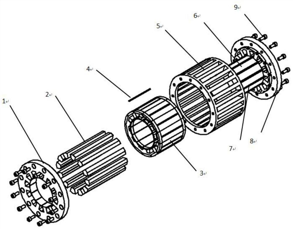
[0064] A method for forming a segmented stator under full-scale control, which includes a set of the same tooling used in the two processes of forming and welding a stator core and a method of using the same, as follows:

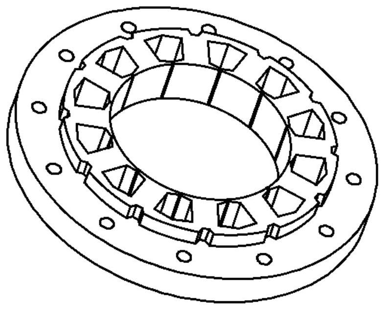
[0065] The tooling includes a mandrel, a notch positioning rod, a toothed positioning rod, an upper pressure plate, a lower pressure plate, a screw and an outer circle fixing hoop. The outer circle fixing hoop is composed of three parts: upper, middle and lower. The circular fixing hoop only uses the upper and lower parts. In the stator core welding process, the outer circular fixing hoop uses the upper, middle and lower parts.

[0066] Press the notch positioning rod into the mandrel, and then match the two with the inner circle part of the lower pressing plate; then insert the toothed positioning rod into the corresponding position of the lower pressing plate.

[0067] Put the laminated stator core into the position corresponding to the tooling in step 2. ...

Embodiment 2

[0074] The invention discloses a method for iron core shaping, which realizes full-scale control of the shape and position tolerance of the iron core through the cooperation of the stator iron core after lamination and the various parts of the tooling.

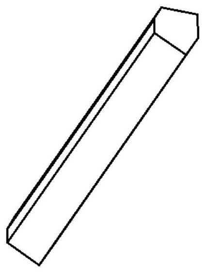
[0075] The method of lamination and shaping of the stator core, through the cooperation of V-shaped buckle and tooling, is used to set the size, which is convenient for the installation of the skeleton, and can ensure that the size error of the core meets the expected requirements after the stator winding is completed.

[0076] One set of tooling is used for two processes. Among them, the outer circle positioning hoop of tooling 5 adopts a three-section block structure. During the iron core shaping process, only the two sections 5-1 and 5-3 in the outer circle positioning hoop of tooling 5 are used. The full-size positioning of several iron core blocks can be achieved by cooperating with other parts of the tooling, and the V-sh...


PUM


Abstract

The invention belongs to the technical field of motor block-type stator manufacturing technology, and discloses a block-shaped stator forming method under full-size control, a block stator and a motor. The inner circle, outer circle and groove shape of the sheet iron core are positioned, and then the punching sheet is pressed and compacted by tightening the screws on the tool, and then the V-shaped buckle is used to crimp the iron core into a whole; then install the stator iron core After the skeleton is completed, the winding is carried out. After the winding is completed, the tooling is used again for full positioning, and then laser welding is used to weld into a full-circle stator. According to the invention, the four parts of the mandrel and the inner circle of the stator iron core, the slot positioning rod and the stator slot, the toothed positioning rod and the outer circle fixing hoop cooperate with each other and the stator iron core. size control. The invention saves the number of tooling, facilitates switching of the tooling, enables reliable forming of the stator iron core and can maintain the size of each part of the stator iron core.

Description

technical field [0001] The invention belongs to the technical field of motor block-type stator manufacturing technology, and particularly relates to a block-type stator forming method, block-type stator and motor under full-size control. Background technique [0002] At present, in order to improve the power density of the permanent magnet synchronous motor and shorten the overall size of the motor, the motor stator is designed in the form of fractional slot concentrated winding. The stator punch of the motor is divided into an average circle according to the number of slots N. After the stator punch of each slot is laminated and formed separately, the skeleton is installed for winding, and finally N pieces of stator punch are spliced ​​into a complete circle, which is heat-fitted with the casing. , forming a complete stator. [0003] At present, the punching sheet self-riveting scheme is mostly adopted for the lamination of each slot stator, which solves the problem of riv...

Claims


Application Information

Patent Timeline
Patent Type & Authority Patents(China)
IPC IPC(8): H02K15/02H02K1/12H02K3/46B23P19/06B23K26/21
CPCH02K15/02H02K1/12H02K3/46B23K26/21B23P19/06
Inventor 汤欢宋宝王坤肖杨陈彪董坤程佳付静静杜成飞
Owner WUHAN HUADA NEW TYPE MOTOR CO LTD
Why Eureka
Try Eureka