
Power supply device for tunnel monitoring system

A system power supply and tunnel monitoring technology, applied in electrical components, friction generators, generators/motors, etc., can solve the problems that restrict the effective use of tunnel airflow power generation devices, cannot be effectively excited, and the airflow velocity changes greatly, and achieves additional The effect of small mass, simple structure and strong adaptability

Active Publication Date: 2021-09-07
广东合泰实业科技有限公司
View PDF6 Cites 3 Cited by
  • Summary
  • Abstract
  • Description
  • Claims
  • Application Information

AI Technical Summary

Problems solved by technology

The airflow in the tunnel can be formed by air convection, or it can be the air flow caused by the high-speed driving of the vehicle. Therefore, the flow velocity of the airflow in the tunnel changes greatly, which seriously restricts the effective use of the existing tunnel airflow power generation device: when the airflow velocity is low, it cannot be Effective excitation, easy to damage due to excessive amplitude when the airflow velocity is too high

Method used


Image

  • Power supply device for tunnel monitoring system
  • Power supply device for tunnel monitoring system
  • Power supply device for tunnel monitoring system

Examples


Embodiment Construction

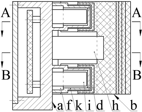
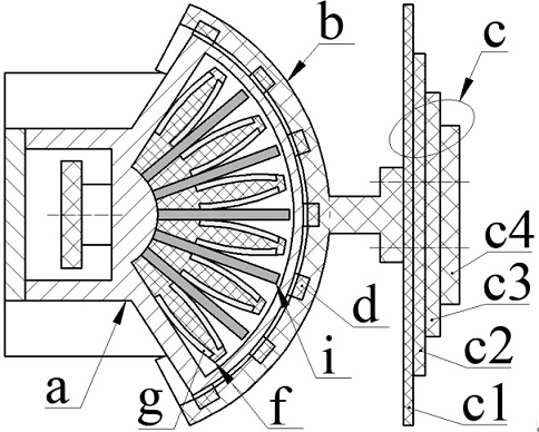
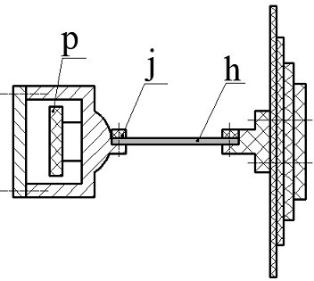
[0031] The present invention proposes a power supply device for a tunnel monitoring system, which mainly includes a frame a, a pendulum b, a coupler c, an end cover k, a magnet d, an elastic vibrator i, an isolator f, a reed h and a circuit board p.

[0032] The column a1 of the frame a is provided with an electric control chamber a2 and two transduction chambers a3, the electric control chamber a2 and the transduction chamber a3 are located on the left and right sides of the column a1, and a circuit board p is installed in the electric control chamber a2; The energy chamber a3 is fan-shaped, and the transduction chamber a3 is surrounded by the bottom wall a31, the side wall a32 and the front wall a33, and a crossbeam a4 is arranged between the bottom walls a31 of the two transduction chambers a3, and the two transduction chambers a3 are arranged symmetrically On the upper and lower sides of the beam a4; the bottom wall a31, two side walls a32 and the front wall a33 constitute ...


PUM


Abstract

The invention relates to a power supply device for a tunnel monitoring system, and belongs to the technical field of new energy. The device mainly comprises a rack, a swing frame, a coupler, an elastic vibrator and an isolator; an electric control cavity and two transduction cavities are formed in the rack, the swing frame is composed of a seat plate, a swing arm and an excitation cavity shell, and a magnet is embedded in the inner wall of the excitation cavity shell; the isolator is composed of a wedge body and a cambered surface body; an end cover is arranged at the end part of the transduction cavity and extrudes the isolator and the elastic vibrator in the transduction cavity; the fixed end of the elastic vibrator and the wedge surface of the isolator extrude each other; the elastic vibrator is composed of a substrate and transduction pieces bonded to the two sides of the substrate; when the transduction plate is a movable friction plate, a fixed friction pair is embedded in the sinking cavity of the isolator, and the fixed friction pair is an independent fixed electrode plate or is formed by bonding the fixed electrode plate and a fixed friction plate; the swing frame is arranged on the rack through a reed, and the coupler is arranged on a seat plate of the swing frame; and when airflow flows through, the coupler drives the swing frame and the magnet to swing in a reciprocating mode, and the elastic vibrator generates reciprocating bending deformation under the action of the magnet and converts mechanical energy into electric energy.

Description

technical field [0001] The invention belongs to the technical field of new energy, and in particular relates to a power supply device for a tunnel monitoring system. Background technique [0002] Tunnels have become an important part of the current road and rail network. In order to ensure the normal and safe passage of cars and trains and to realize the real-time monitoring of the tunnel environment and passing vehicles, various instruments and lighting facilities need to be installed in the tunnel, so there must also be corresponding power supply facilities in the tunnel. At present, cables are commonly used for power supply. The laying of cables and subsequent maintenance are difficult and costly. The most critical thing is that the monitoring system will not be able to operate normally when the power supply system fails. Therefore, people have successively proposed various forms of devices that utilize tunnel airflow to generate electricity, and generate electricity thr...

Claims


Application Information

Patent Timeline
Patent Type & Authority Applications(China)
IPC IPC(8): H02N2/18H02N1/04F03G7/08
CPCH02N2/186H02N1/04F03G7/08
Inventor 张忠华李哲谷一群张海琪陈松王淑云曾平吴鸣程光明
Owner 广东合泰实业科技有限公司
Learn More