
Liquid cooling plate radiator

A radiator and liquid cooling plate technology, applied in cooling/ventilation/heating transformation, electrical components, electrical equipment structural parts, etc. limited issues

Active Publication Date: 2021-09-07
SHENZHEN MICROBT ELECTRONICS TECH CO LTD
View PDF14 Cites 2 Cited by
  • Summary
  • Abstract
  • Description
  • Claims
  • Application Information

AI Technical Summary

Problems solved by technology

[0006] That is to say, in view of the above-mentioned technical problem that when the cooling sub-channel is in a single linear shape, the heat dissipation area of ​​the cooling liquid is limited and the heat dissipation efficiency is not high when the cooling liquid flows through the cooling sub-channel, the embodiment of the present application adopts A number of fin units are arranged in front and rear dislocations along the flow direction of the cooling liquid on the heat sink sub-channel, so that, on the one hand, the fins of the fin unit increase the contact area between the radiator of the liquid cold plate and the cooling liquid, thereby improving On the other hand, the fins of the front and rear adjacent fin units are misplaced, which causes the coolant to flow between the two adjacent fin units when it flows from the previous fin unit to the next fin unit. It is easy to understand that this disturbance enhances the convective heat transfer intensity of the cooling liquid, thereby enhancing the heat transfer effect between the cooling liquid and the fin unit; The single linear shape leads to technical problems such as limited heat dissipation area and low heat dissipation efficiency, which effectively improves the contact area between the liquid cold plate radiator and the coolant, and improves the heat dissipation efficiency by increasing the disturbance of the coolant, with a simple structure

Method used


Image

  • Liquid cooling plate radiator
  • Liquid cooling plate radiator
  • Liquid cooling plate radiator

Examples


Embodiment Construction

[0065] In order to better understand the above-mentioned technical solutions, the exemplary embodiments of the present application will be described in detail below with reference to the accompanying drawings. Obviously, the described embodiments are only part of the embodiments of the present application, rather than all embodiments of the present application. It is understood that the application is not limited by the exemplary embodiments described herein.

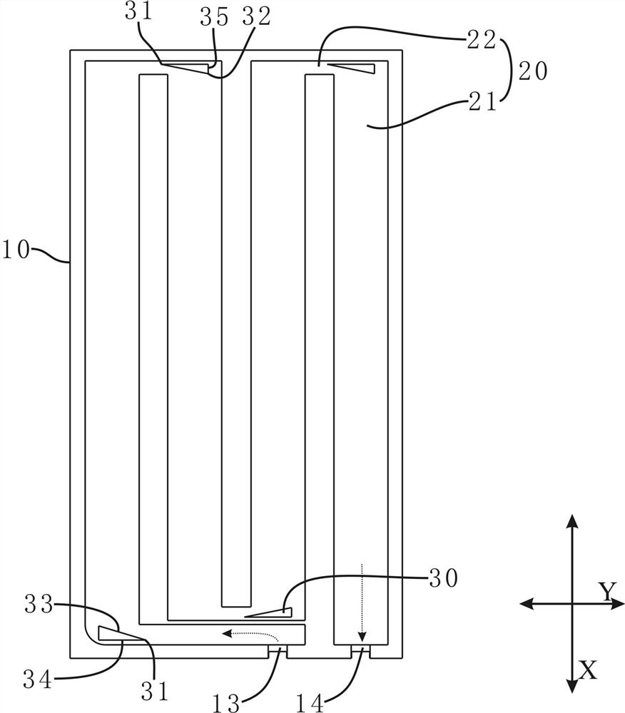
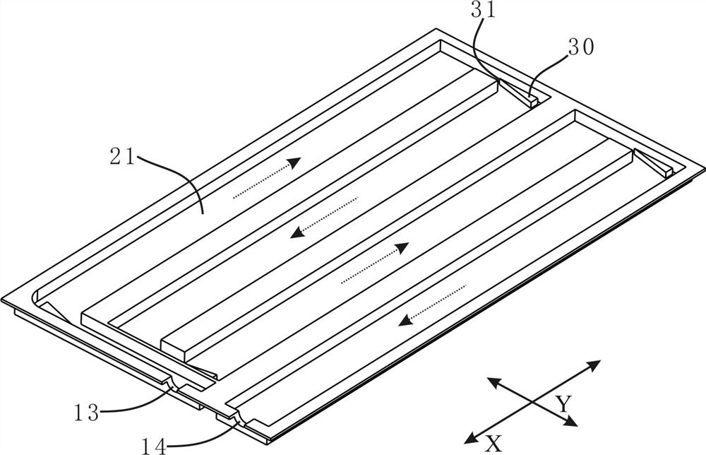
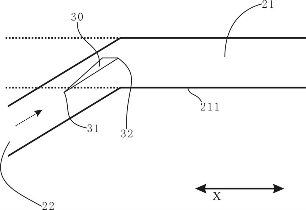
[0066] Please combine first figure 1 as well as Figure 6~Figure 9 , the embodiment of the present application discloses a liquid-cooled plate radiator, the liquid-cooled plate radiator includes a radiator body 10, a cooling liquid flow channel 20 and a fin unit 40; the cooling liquid flow channel 20 is formed on the radiator body 10 Inside, the cooling liquid channel 20 is used for circulating the cooling liquid, and the cooling liquid channel 20 includes a plurality of cooling sub-channels 21; several fin units 40 ar...


PUM


Abstract

The invention discloses a liquid cooling plate radiator which comprises a radiator body, a cooling liquid flow channel is formed in the radiator body, and the cooling liquid flow channel is used for allowing cooling liquid to flow circularly, wherein the cooling liquid flow channel comprises a plurality of cooling sub-flow channels, then a plurality of fin units are arranged on the cooling sub-flow channels in the flowing direction of cooling liquid, each fin unit is provided with a plurality of fins extending side by side in the flowing direction of the cooling liquid, and the fins of the front-back adjacent fin units on the cooling sub-flow channels are arranged in a staggered mode. Therefore, the heat dissipation area is increased, the disturbance of the cooling liquid flowing in the heat dissipation sub-flow channels is enhanced, and the heat dissipation efficiency is improved; and therefore, the technical problems of limited heat dissipation area, low heat dissipation efficiency and the like caused by a single linear cooling liquid flow channel are solved, the contact area between the liquid cooling plate radiator and the cooling liquid is effectively increased, the heat dissipation efficiency is improved by increasing the disturbance of the cooling liquid, and the structure is simple.

Description

technical field [0001] The invention relates to the technical field of liquid cooling and heat dissipation, in particular to a liquid cooling plate radiator. Background technique [0002] At present, more and more electronic devices adopt liquid cooling to dissipate heat. [0003] In the prior art, a common liquid-cooled heat dissipation method is to use a liquid-cooled plate to dissipate heat. For example, attach a hashboard with chips and other heating elements attached to one or both sides of the liquid-cooled plate, and then the cooling liquid flows in from the inlet. Inside the liquid-cooled plate, the cooling liquid flows through the channel and then flows out from the outlet, so that the circulating flow realizes the liquid cooling and heat dissipation of the power plate. [0004] However, in the above solution, the coolant flow channel of the liquid cooling plate is usually linear, the flow channel is single, and the heat dissipation area is limited, which leads to ...

Claims


Application Information

Patent Timeline
Patent Type & Authority Applications(China)
IPC IPC(8): H05K7/20
CPCH05K7/20263H05K7/20272H05K7/20409F28D1/0308F28D2021/0029F28F3/12H05K7/20254
Inventor 陈前刘方宇高阳巫跃凤宁洪燕
Owner SHENZHEN MICROBT ELECTRONICS TECH CO LTD
Learn More