Emergency bandaging supporting equipment for emergency nursing

A support device and emergency technology, applied in medical science, bandages, etc., can solve problems affecting the best effect of bandaging, increasing the burden of bandaging work for medical staff, and difficult to quickly complete bandaging work, etc.

Active Publication Date: 2021-09-10
谢晓筠
View PDF10 Cites 0 Cited by
  • Summary
  • Abstract
  • Description
  • Claims
  • Application Information

AI Technical Summary

Problems solved by technology

[0002] Patients with arm, leg or ankle injuries generally need to use bandages for bandages. Traditional bandages are medical staff who hold bandages and wrap them around the injured limbs of patients. Reciprocating bandages often make the hands and arms of medical staff sore. During the process, sometimes the bandages will be wound unevenly, and the bandages will be too loose or too tight, which will increase the burden on the medical staff and affect the best effect of the bandage. When it is necessary to bandage the patient's limbs urgently, manual bandaging is difficult to complete quickly. Bandaging work, especially when bandaging the ankle, not only needs to bandage the instep and the sole of the foot but also the calf above the ankle. Manual bandaging is time-consuming and laborious. Although some bandaging support equipment can automatically bandage the arm, this type of equipment cannot be used on the arm, Flexible switching of dressing bandages between legs and ankles, it is difficult to meet the needs of emergency dressing

Method used


Image

  • Emergency bandaging supporting equipment for emergency nursing
  • Emergency bandaging supporting equipment for emergency nursing
  • Emergency bandaging supporting equipment for emergency nursing

Examples


Embodiment Construction

[0028] The technical solutions in the embodiments of the present invention will be clearly and completely described below in conjunction with the embodiments of the present invention. Apparently, the described embodiments are only some of the embodiments of the present invention, not all of them. Based on the embodiments of the present invention, all other embodiments obtained by persons of ordinary skill in the art without creative efforts fall within the protection scope of the present invention.

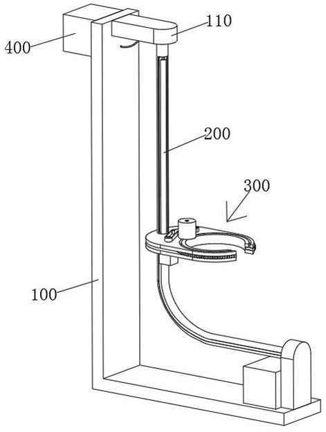
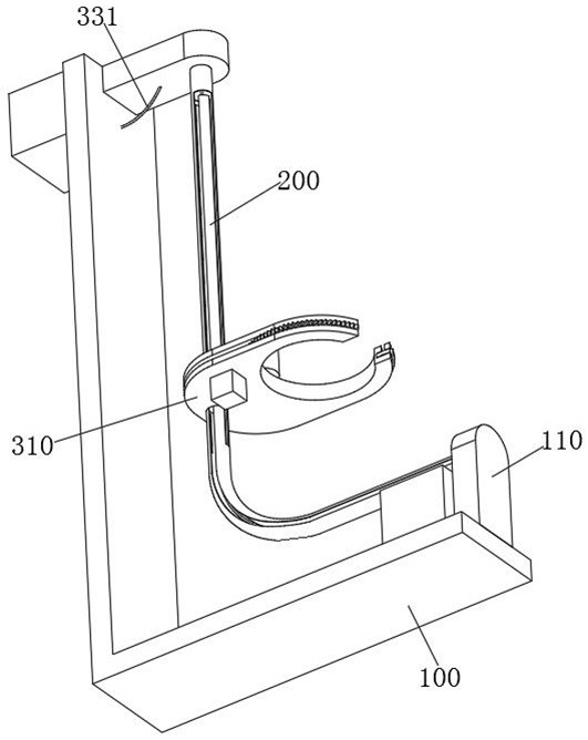
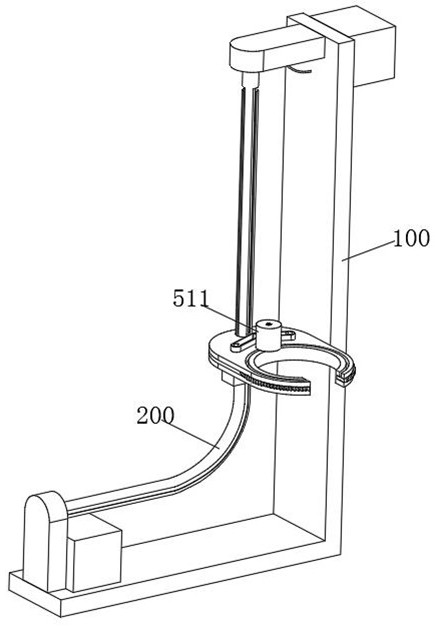
[0029] see Figure 1-9As shown, an emergency bandage support device for emergency care, including an L-shaped support plate 100, the inner side of the top of the L-shaped support plate 100 and the top surface of the bottom are fixedly connected with a connecting seat 110, and the two connecting seats 110 are fixedly connected. There is a guide elbow 200, the outer wall of the guide elbow 200 is provided with a sliding seat 300, the sliding seat 300 includes a base plate 310 and a ...


PUM


Abstract

The invention relates to the technical field of medical equipment, and specifically relates to emergency bandaging supporting equipment for emergency nursing. The equipment comprises an L-shaped supporting plate, connecting seats are fixedly connected to the inner side of the top of the L-shaped supporting plate and the top surface of the bottom of the L-shaped supporting plate, a guide bent pipe is fixedly connected between the two connecting seats, a sliding seat is arranged on the outer side wall of the guide bent pipe, the sliding seat comprises a bottom plate and a top plate which are in sliding connection with the outer side wall of the guiding bent pipe, and a sliding ball which is in sliding connection with the inner side wall of the guiding bent pipe is arranged between the bottom plate and the top plate. According to the invention, an arc-shaped winding gear drives a bandage rolling wheel on the top face of the arc-shaped winding gear to do circular motion on the outer side of an arm or a leg through a driving mechanism, first motors in two first machine boxes are matched with each other to rotate to release or wind a traction rope, a sliding base and the arc-shaped winding gear on the sliding base move along a guiding bent pipe, bandages on the bandage winding wheel are evenly wound on limbs, manual bandage winding is omitted, and the bandage winding efficiency is improved.

Description

technical field [0001] The invention relates to the technical field of medical equipment, in particular to an emergency dressing support equipment for emergency care. Background technique [0002] Patients with arm, leg or ankle injuries generally need to use bandages for bandages. Traditional bandages are medical staff who hold bandages and wrap them around the injured limbs of patients. Reciprocating bandages often make the hands and arms of medical staff sore. During the process, sometimes the bandages will be wound unevenly, and the bandages will be too loose or too tight, which will increase the burden on the medical staff and affect the best effect of the bandage. Bandaging work, especially when bandaging the ankle, must not only bandage the instep and the sole of the foot but also the calf above the ankle. Manual bandaging is time-consuming and laborious. Although some bandaging support equipment can automatically bandage the arm, this type of equipment cannot be used...

Claims


Application Information

Patent Timeline
Patent Type & Authority Applications(China)
IPC IPC(8): A61F15/00
CPCA61F15/005
Inventor 谢晓筠张园张燕翔
Owner 谢晓筠
Why Eureka
Try Eureka