Supercharge Your Innovation With Domain-Expert AI Agents!

Thrust mechanism, automatic injection device applying same and use method of automatic injection device

An automatic injection and thrust technology, applied in the direction of automatic injectors, syringes, hypodermic injection devices, etc., can solve the problems of loss of limit parts, self-locking after the product cannot be guaranteed, poor patient compliance, etc.

Active Publication Date: 2021-09-10
NINGBO COMFORT-INFUSTION MEDTECH CO LTD
View PDF8 Cites 1 Cited by
  • Summary
  • Abstract
  • Description
  • Claims
  • Application Information

AI Technical Summary

Problems solved by technology

This method requires energy consumption, high cost of use, complex control system, and the need to use batteries will cause environmental pollution
Connecting with various transmission mechanisms will cause the overall volume of the product to be large, which cannot meet the requirements of portability and ease of use
[0004] 2. At present, in order to achieve multi-dimensional feedback, most of the related products on the market rely on electronic components to complete visual and auditory feedback, and the products still need battery power.
If the product cannot achieve its proper function when used in an environment with strong electromagnetic interference
Electronic components are easily affected by the environment, easy to age, and should not be stored for a long time
It is difficult to guarantee the stability and reliability of the entire device when used in a complex environment
[0005] 3. At present, there are many operation steps for such products on the market, often requiring at least three or more operation steps. Patients still have the risk of forgetting after periodic use, and patients' compliance is poor.
However, in some specific cases, there will be phenomena such as loss of limiting parts and patients forgetting to operate, so that the product cannot ensure that it is self-locking after use.
And this design is contrary to human factors engineering and does not conform to the design characteristics of this type of product
[0007] 5. In order to realize the automatic injection function of the existing products, most of the trigger mechanisms adopt buckle and other structural designs, and use the elastic deformation of the parts to complete the triggering and locking processes. This design often requires the buckle and other structures to be in a state of compression and deformation. This type of product is one-time use, and the parts are usually injection molded from polymer materials. The buckle structure of the parts is under pressure, which is not conducive to transportation and long-term storage, and is greatly affected by the environment. Such structures are prone to plastic deformation.
When it is used, it loses its proper elasticity, so it cannot reach its proper position, resulting in product failure
[0008] 6. Existing products use parts to impact and produce sound feedback. The power source is the same as that of injection power, which is likely to cause jamming and uneven power distribution. The product will have too long injection time and low feedback volume. Unable to grasp the injection process, end the injection early, and the drug solution cannot be injected into the patient's body according to the prescribed dose, thereby reducing the curative effect
However, in this invention, the stopping elements used for vocal feedback are continuously distributed, and they are always vocal from the beginning of the injection to the end of the injection, and there is no obvious distinction, which is likely to cause confusion for the patient and cannot accurately identify the injection state

Method used


Image

  • Thrust mechanism, automatic injection device applying same and use method of automatic injection device
  • Thrust mechanism, automatic injection device applying same and use method of automatic injection device
  • Thrust mechanism, automatic injection device applying same and use method of automatic injection device

Examples


Embodiment 1

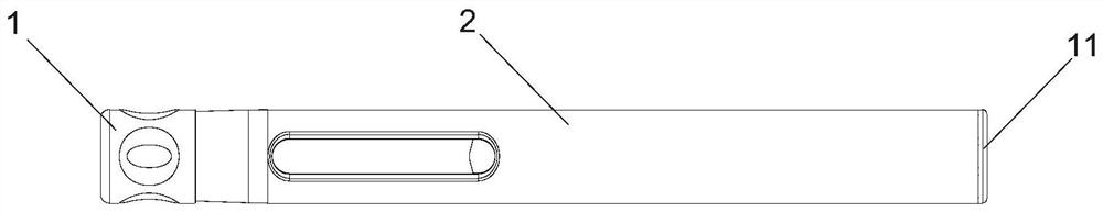
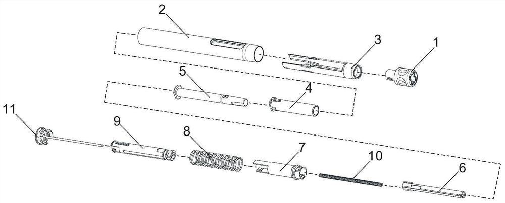
[0079] like Figure 1 to Figure 16 As shown, an automatic injection device includes a head-end protective cap 1, a safety sleeve 3, a casing 2, a protective casing 4, a prefilled syringe 5, a push rod 6, a reciprocating sleeve 7, a return spring 8, and a sounding guide assembly 9 and the bottom cover 11, the injection spring 10 is arranged between the push rod 6 and the bottom cover 11, the head end protective cap 1, the safety sleeve 3, the shell 2 and the protective shell 4 constitute the housing assembly, the push rod 6, the reciprocating sleeve 7 , return spring 8, sound guide assembly 9 and bottom cover 11 constitute a thrust mechanism with automatic feedback function, the front end of push rod 6, that is, the end towards the prefilled syringe 5 is the output end of the thrust mechanism, and the prefilled syringe 5 and the thrust mechanism are arranged in the cavity of the shell assembly. Safety sleeve 3, shell 2, protective shell 4, prefilled syringe 5, push rod 6, reci...

Embodiment 2

[0090] like Figures 17 to 19d As shown, the tile-shaped long cantilever is provided with a hollow area, the hollow area is provided with a safety sleeve self-locking cantilever 33, and the safety sleeve self-locking cantilever 33 is provided with a self-locking bump 34, and the self-locking structure is provided with On the housing assembly, the self-locking structure includes a safety sleeve self-locking cantilever 33 disposed on the safety sleeve 2 and a lock block 24 disposed on the inner wall of the housing 3, and the lock block 24 protrudes radially on the inner wall of the housing 3 , the lock block 24 is V-shaped as a whole, and the lock block 24 is provided with a starting side wall 241 and a reset side wall 242 intersecting at the rear end of the lock block 24, and the starting side wall 241 and the reset side wall 242 intersect to form a sharp point 245 after the lock block, A V-shaped groove 243 is formed at the front end of the locking block 24 . The starting sid...

Embodiment 3

[0095] The front end surface 924 of the anti-retraction block is a plane perpendicular to the axis of the sounding ring 93 . All the other are with embodiment 1.


PUM


Abstract

The invention discloses a thrust mechanism with an automatic feedback function. The thrust mechanism comprises a push rod, a reciprocating sleeve, a reset spring and a bottom cover, wherein the reset spring sleeves the reciprocating sleeve, an injection spring is arranged between the push rod and the bottom cover, the reciprocating sleeve can lock the push rod before the push rod is started and pushed and can retreat to release the push rod. The thrust mechanism further comprises a sound production guide assembly, wherein the push rod, the reciprocating sleeve and the sound production guide assembly are coaxially nested in a sliding mode, the sound production guide assembly can lock the reciprocating sleeve after the reciprocating sleeve reciprocates once, and the sound production guide assembly and the push rod act to generate starting prompt sound and stopping prompt sound separately during starting and stopping of pushing of the push rod. The invention further discloses an automatic injection device applying the thrust mechanism with the automatic feedback function and a use method of the automatic injection device.

Description

technical field [0001] The present invention relates to a new type of drug delivery device for self-management of diseases by patients, more specifically, it relates to a thrust mechanism with automatic feedback function, an automatic injection device using the thrust mechanism with automatic feedback function, and the automatic injection device usage method. Background technique [0002] With the explosive growth of population, the siphon effect of cities, and the increasing shortage of medical resources, the management of chronic diseases will occupy a large amount of medical resources, resulting in huge economic costs. Society has put forward higher requirements for injection devices used by patients themselves. People hope that the operation of injection devices is as simple as possible and does not require special training. Traditional injection devices usually require proficiency in the angle and depth of needle insertion, and manual injection, resulting in a certain ...

Claims


Application Information

Patent Timeline
IPC IPC(8): A61M5/20A61M5/31A61M5/315A61M5/32
CPCA61M5/2033A61M5/31A61M5/3158A61M5/3202A61M5/3257A61M2205/581A61M2205/583
Inventor 王佩儿
Owner NINGBO COMFORT-INFUSTION MEDTECH CO LTD
Features
  • R&D
  • Intellectual Property
  • Life Sciences
  • Materials
  • Tech Scout
  • Unparalleled Data Quality
  • Higher Quality Content
  • 60% Fewer Hallucinations
Learn More