High-pressure foam generating device suitable for underground operation under different working conditions and preparation method thereof
A technology of foam generating device and working conditions, which is applied in the direction of mixing methods, chemical instruments and methods, earthwork drilling and mining, etc., and can solve the problems of cost control, production preparation and safety operation inconvenience, etc.
Active Publication Date: 2021-09-10
CHINA NAT PETROLEUM CORP CHUANQING DRILLING ENG CO LTD +1
View PDF23 Cites 0 Cited by
- Summary
- Abstract
- Description
- Claims
- Application Information
AI Technical Summary
Problems solved by technology
[0004] Due to the above reasons, the existing high-pressure foam generators cannot meet the above requirements at the same time, which leads to the need to prepare different models or specificatio
Method used
View moreImage
Smart ImageViewing Examples

Examples
 PUM
| Property | Measurement | Unit |
|---|---|---|
| Radius | aaaaa | aaaaa |
| Radius | aaaaa | aaaaa |
| Radius | aaaaa | aaaaa |
Abstract
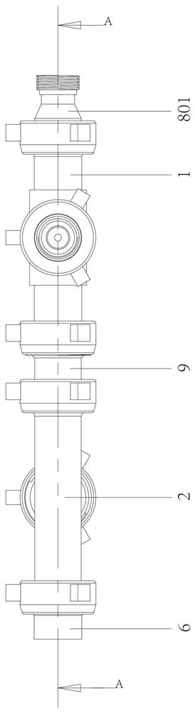
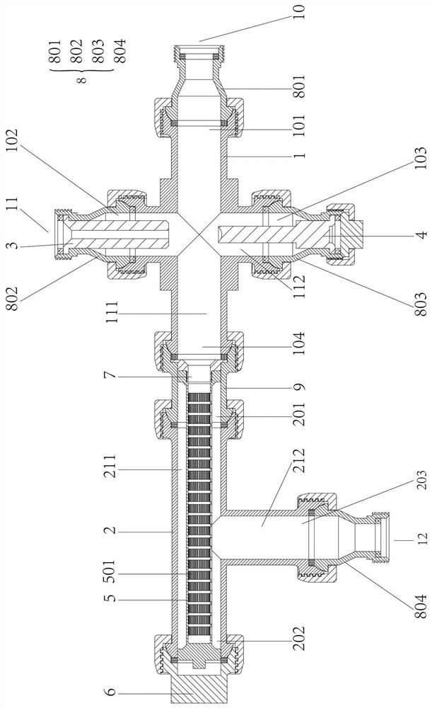
The invention provides a high-pressure foam generating device suitable for underground operation under different working conditions and a preparation method thereof. The device comprises a cross-shaped four-way joint, a T-shaped three-way joint, a liquid nozzle, a turbulent flow rod, a screen pipe and a plug, wherein the cross-shaped four-way joint is connected with the T-shaped three-way joint. The liquid nozzle is a tubular column body, is arranged in a channel of the cross-shaped four-way joint and can spray liquid into the cross-shaped four-way joint; and the turbulent flow rod is arranged in the three channels of the cross-shaped four-way joint, is coaxial with the liquid nozzle and is configured to be capable of changing the flow direction of the liquid sprayed by the liquid nozzle, and the screen pipe is arranged in a channel of the T-shaped three-way joint. The method comprises the step of using the high-pressure foam generating device and comprises the steps: pumping a foam base liquid into the cross-shaped four-way joint from a high-pressure liquid phase inlet; and inputting high-pressure gas into the cross-shaped four-way joint from a high-pressure gas phase inlet. The device has the beneficial effect that the device can be suitable for underground operation under different working conditions.
Description
technical field [0001] The invention relates to the technical field of downhole operations in oil and gas fields, in particular to a high-pressure foam generating device suitable for downhole operations under different working conditions and a preparation method. Background technique [0002] As a compressible non-Newtonian fluid, foam fluid has been widely used in drilling, completion and stimulation of oil and gas wells because of its unique structural and seepage characteristics. Among the various methods of generating high-pressure foam fluid, mixing gas and foam base liquid under high pressure is one of the most commonly used methods. The device that realizes the mixing of gas and foam base liquid under high pressure and promotes its foaming is called It is a high-pressure foam generating device. [0003] With the continuous improvement of downhole operation technology, the performance requirements for high-pressure foam fluid are becoming more and more diverse, which ...
Claims
Login to View More Application Information
Patent Timeline
 IPC IPC(8): B01F3/04B01F13/06B01F13/10B01F13/04E21B43/16B01F35/60
CPCE21B43/166
Inventor 方福君陆灯云李剑秋王爽刘伟卢秀德方泽本李源源管彬刘志尧尹丛彬陈明忠熊杰
Owner CHINA NAT PETROLEUM CORP CHUANQING DRILLING ENG CO LTD