
Transmission structure of multi-arm manipulator

A technology of transmission structure and manipulator, applied in manipulators, program control manipulators, manufacturing tools, etc., can solve problems such as damage to electrical components

Inactive Publication Date: 2021-09-10
HARBIN KENENG CLADDING TECH +2
View PDF5 Cites 0 Cited by
  • Summary
  • Abstract
  • Description
  • Claims
  • Application Information

AI Technical Summary

Problems solved by technology

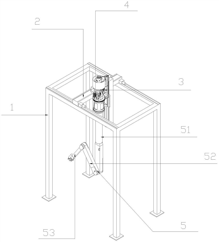
[0003] In view of this, the present invention aims to propose a transmission structure of a multi-arm manipulator to solve the problem of damage to the electrical components driven by the manipulator under high temperature conditions

Method used


Image

  • Transmission structure of multi-arm manipulator
  • Transmission structure of multi-arm manipulator
  • Transmission structure of multi-arm manipulator

Examples


Embodiment Construction

[0027] It should be noted that the features in the present invention in the present invention can be combined with each other in the case of an unable conflict.

[0028] In the description of the present invention, it is to be understood that the terms "center", "longitudinal", "horizontal", "upper", "lower", "front", "post", "left", "right", " The orientation of the orientation of the orientation of the direction "," horizontal "," top "," bottom "," inside "," outside ", etc. is based on the orientation or positional relationship shown in the drawings, is only for convenience of describing the present invention and Simplify the description, rather than indicating or implying that the device or element must have a specific orientation, constructed and operated in a particular direction, and thus is not to be construed as limiting the invention. Moreover, the terms "first", "second", etc. are only used to describe purposes, and cannot be understood as an indication or implies rela...


PUM


Abstract

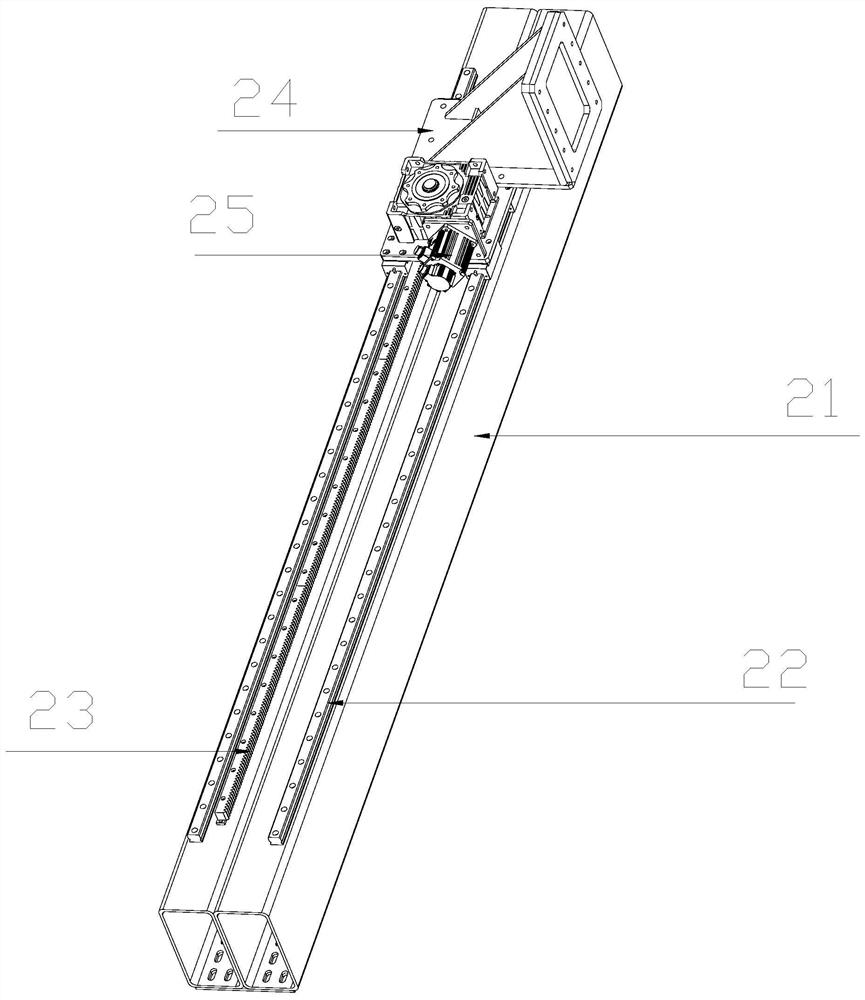
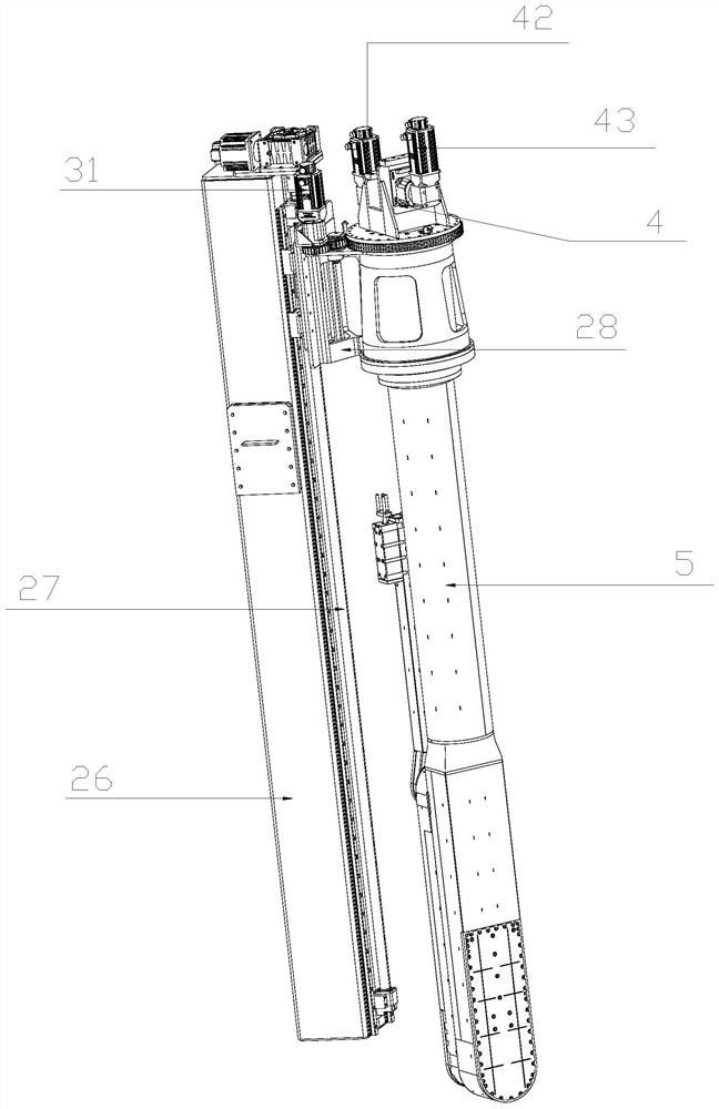
The invention provides a transmission structure of a multi-arm manipulator. The transmission structure comprises a support, an XYZ three-direction transmission device, a rotating assembly and a multi-arm transmission device, wherein the XYZ three-direction transmission device is fixedly installed at the upper end of the support, a high-temperature furnace is arranged at the lower end of the support, one sides of the XYZ three-direction transmission device are slidably connected with a working arm assembly, the rotating assembly and the multi-arm transmission device, a cleaning unit is installed at the lower end of the working arm assembly, the cleaning unit is located in the high-temperature furnace after the working arm assembly is unfolded, the XYZ three-direction transmission device provides three-direction displacement power for the working arm assembly, the rotating assembly provides rotating power for the working arm assembly, and the multi-arm transmission device provides unfolding power for the working arm assembly. According to the transmission structure of the multi-arm manipulator, the XYZ three-direction transmission device, the multi-arm transmission device and the rotating assembly are all located outside the high-temperature furnace, so that damage to transmission electrical parts caused by the high-temperature working condition is prevented, the service life of the working arm assembly is prolonged, and operation safety and stability are guaranteed.

Description

Technical field [0001] The present invention belongs to the field of multi-arm robot drive technology, especially relates to a transmission structure of a multi-arm robot. Background technique [0002] Boiler combustion equipment as commonly used, which during operation, having a high temperature furnace, alkali, acid, fouling, etc., likely to cause wear and corrosion of the furnace wall, thus affecting the heat transfer coefficient, reducing the thermal efficiency of the boiler, causing high temperature corrosion and increasing emissions of gaseous pollutants, can cause more serious when the unit down load operation or shutdown, or even cause boiler tube explosion and other dangerous accidents. So use a great impact on the boiler and safety. Therefore, the use of boilers companies, after a certain period of time the boiler use, require shutdown of the inner wall of the boiler maintenance and cleaning, general waste incinerator to be shutdown at least twice a year. Maintenance sh...

Claims


Application Information

Patent Timeline
Patent Type & Authority Applications(China)
IPC IPC(8): B25J9/10B25J19/00
CPCB25J9/10B25J19/00
Inventor 展乾王波
Owner HARBIN KENENG CLADDING TECH
Learn More