
Round stick section drilling equipment

A kind of drilling equipment and cross-section technology, which is applied in the field of round stick cross-section drilling equipment, can solve the problems of troublesome and laborious, round sticks scattered on the ground, etc.

Active Publication Date: 2021-09-10
南京祥鑫固废利用科技有限公司
View PDF5 Cites 2 Cited by
  • Summary
  • Abstract
  • Description
  • Claims
  • Application Information

AI Technical Summary

Problems solved by technology

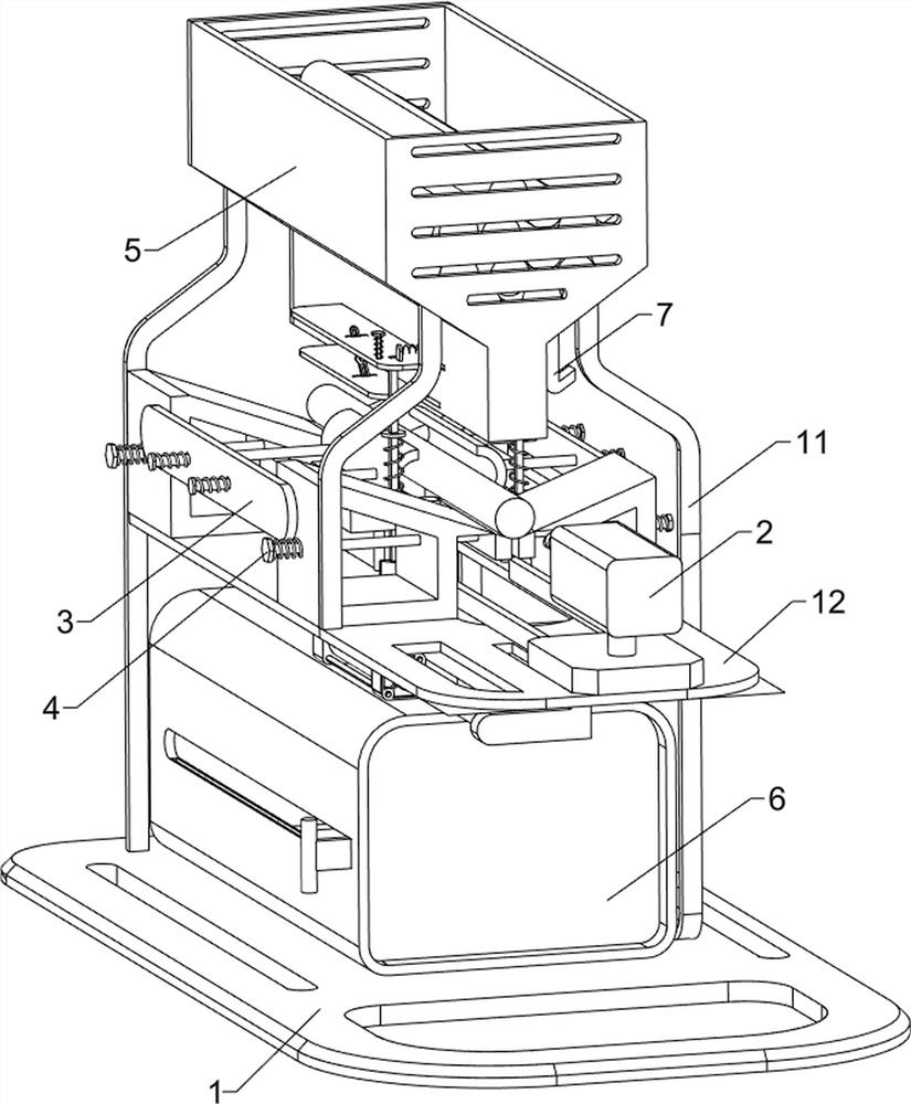
[0005] In order to overcome the disadvantages of the prior art that hand-held round sticks are manually loaded repeatedly, which is troublesome and laborious, the round sticks are scattered on the ground, and it is necessary to observe the feeding situation of the round sticks for a long time. The technical problem of the present invention is to provide a Drilling holes in the cross-section of round sticks, convenient for placing round sticks, automatic quantitative cutting, convenient for receiving and collecting materials, and automatic reminder for round stick cross-section drilling equipment for insufficient round sticks

Method used


Image

  • Round stick section drilling equipment
  • Round stick section drilling equipment
  • Round stick section drilling equipment

Examples


Embodiment 1

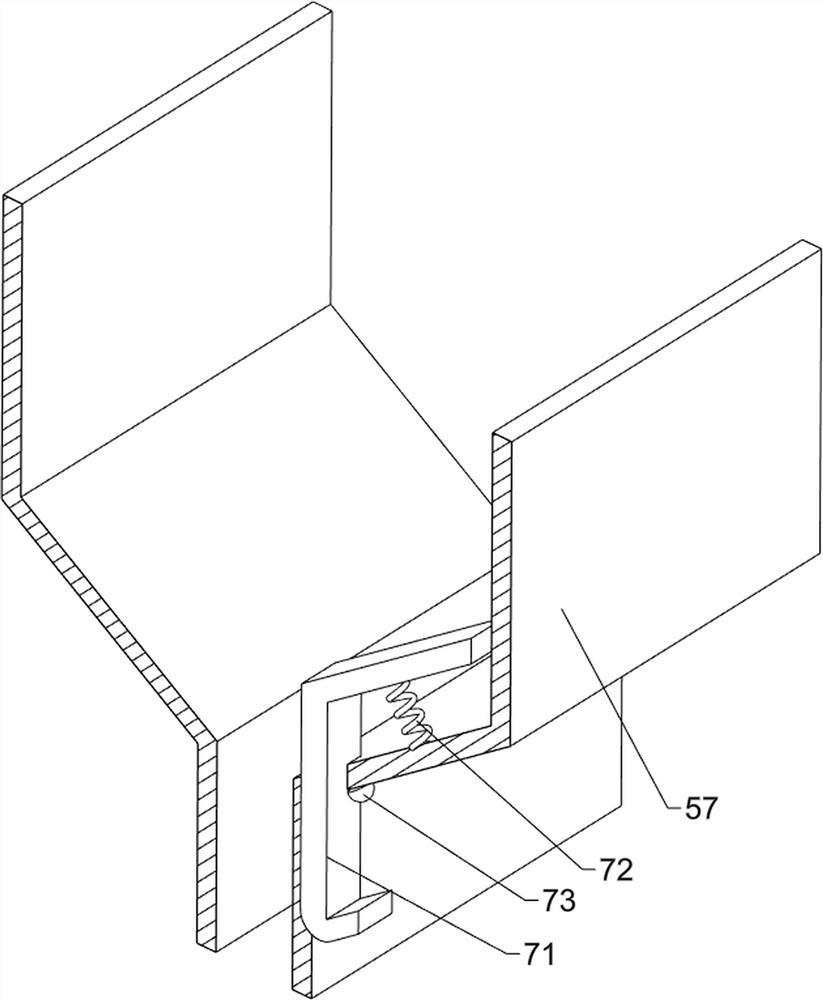
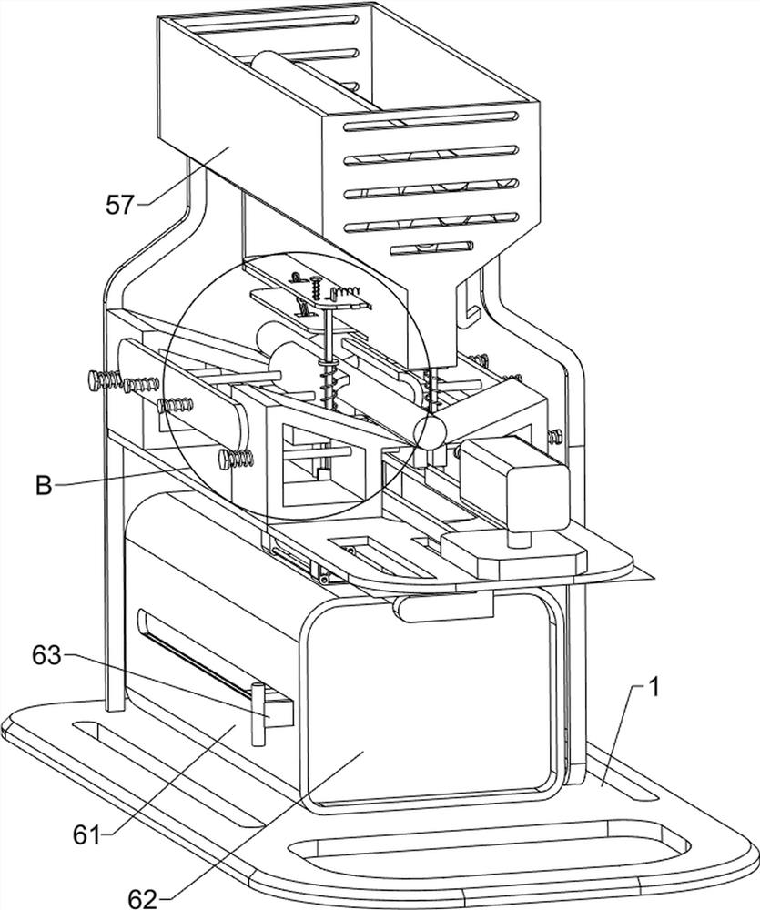
[0028] A kind of round wooden stick section drilling equipment, such as figure 1 , figure 2 with image 3 As shown, it includes a base plate 1, a support frame 11, a workbench 12, a drilling mechanism 2 and a clamping mechanism 3. The upper left side of the base plate 1 is connected with a support frame 11, and the middle part of the support frame 11 is connected with a workbench 12. The workbench 12 A drilling mechanism 2 is arranged on it, and a clamping mechanism 3 is arranged on the drilling mechanism 2 .

[0029] The drilling mechanism 2 includes a cylinder 21, a slide plate 22, a drilling machine 23, a first connecting block 24 and a placement table 25, the right front side of the bottom of the workbench 12 is equipped with a cylinder 21, and the right side of the piston rod of the cylinder 21 is connected with the first connecting block 24 , the first connecting block 24 is slidingly connected to the workbench 12, the upper part of the first connecting block 24 is co...

Embodiment 2

[0033] On the basis of Example 1, such as figure 1 , Figure 4 , Figure 5 with Image 6As shown, it also includes a blanking assembly 4, and the blanking assembly 4 includes a fourth connecting rod 41, a gear bar 42, a second spring 43, a fifth connecting rod 44, a third spring 45 and a second connecting block 46, placed A fourth connecting rod 41 is slidably connected to the middle part of the table 25, a second spring 43 is connected between the outside of the fourth connecting rod 41 and the placement table 25, and a gear lever is connected between the inside of the fourth connecting rod 41 on the front and rear sides. 42, the fifth connecting rod 44 is slidingly connected to the right side of the gear lever 42, and the fifth connecting rod 44 cooperates with the first connecting rod 31, and the middle part of the fifth connecting rod 44 is connected with a second connecting block 46, and the second connecting A third spring 45 is connected between the block 46 and the ...


PUM


Abstract

The invention relates to drilling equipment, in particular to round stick section drilling equipment. To solve the technical problem, the invention provides round stick section drilling equipment, which easily completes round wood stick section drilling, automatically places round wood sticks, achieves automatic quantitative discharging, conveniently receives and collects materials and automatically reminds the situation that round wood sticks are insufficient. The round stick section drilling equipment comprises: a bottom plate, wherein one side of the upper portion of the bottom plate is connected with a supporting frame; a workbench, wherein the middle part of the supporting frame is connected with the workbench; a drilling mechanism which is arranged on the workbench; and a clamping mechanism which is arranged on the drilling mechanism. According to the round stick section drilling equipment provided in the invention, after round sticks fall into a discharging box and are stacked to a certain amount, a handle and a push plate are pushed to move leftwards, so that the round sticks are pushed out of the discharging box and collected in a unified mode, and thus, the effects that materials are conveniently collected and pushed out and collected in a unified mode are achieved, and the round sticks can be prevented from being broken.

Description

technical field [0001] The invention relates to a drilling device, in particular to a drilling device for a section of a round stick. Background technique [0002] In the fields of construction and manufacturing, it is often necessary to use a variety of parts, and sometimes in order to facilitate the better use of parts in various fields, they will be processed, including the section of a certain round stick drilling. [0003] The existing drilling technology for the cross-section of the round stick usually starts the drilling rig after holding the round stick to a suitable position, and after the round stick is clamped, the drilling rig is used to drill the round stick. It is troublesome and labor-intensive. Secondly, it is labor-intensive to continuously load materials manually, resulting in low drilling efficiency. The drilled round wooden sticks fall directly to the ground, scattered and disorderly. At the same time, the round wooden sticks may be damaged. Finally, it ...

Claims


Application Information

Patent Timeline
IPC IPC(8): B27C3/02B65G47/14B65G43/08B65G65/44B65G47/82
CPCB27C3/02B65G47/1442B65G43/08B65G65/44B65G47/82Y02P70/10
Inventor 潘利锋
Owner 南京祥鑫固废利用科技有限公司
Learn More