Eureka AIR delivers breakthrough ideas for toughest innovation challenges, trusted by R&D personnel around the world.

Conveying system of injection molding belt line

A conveying system and belt technology, applied in the direction of conveyors, conveyor objects, transportation and packaging, etc., can solve problems such as low efficiency

Active Publication Date: 2021-09-10
ZHUHAI GREE INTELLIGENT EQUIP CO LTD +1
View PDF9 Cites 0 Cited by
  • Summary
  • Abstract
  • Description
  • Claims
  • Application Information

AI Technical Summary

Problems solved by technology

[0004] The main purpose of the present invention is to provide a conveying system for injection molding belt line to solve the problem of low efficiency in product conveying in the prior art

Method used


Image

  • Conveying system of injection molding belt line
  • Conveying system of injection molding belt line
  • Conveying system of injection molding belt line

Examples


Embodiment Construction

[0024] It should be noted that, in the case of no conflict, the embodiments in the present application and the features in the embodiments can be combined with each other. The present invention will be described in detail below with reference to the accompanying drawings and examples.

[0025] It should be noted that, unless otherwise specified, all technical and scientific terms used in this application have the same meaning as commonly understood by those of ordinary skill in the art to which this application belongs.

[0026] In the present invention, unless stated otherwise, the used orientation words such as "upper, lower, top, bottom" are usually for the directions shown in the drawings, or for the parts themselves in the vertical, In terms of vertical or gravitational direction; similarly, for the convenience of understanding and description, "inner and outer" refer to the inner and outer relative to the outline of each component itself, but the above orientation words ...


PUM


Abstract

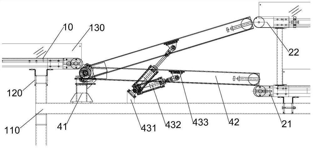
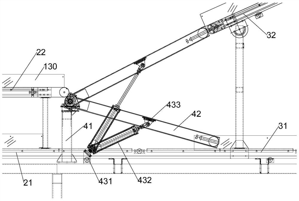
The invention provides a conveying system of an injection molding belt line. The conveying system of the injection molding belt line comprises a conveying belt line and at least one turnover mechanism; the conveying belt line is arranged at an outlet of an injection molding machine, the conveying belt line comprises multiple sections of sub-conveying belt lines, and at least one section of the multiple sections of sub-conveying belt lines is of a multi-layer conveying structure; and the turnover mechanisms are arranged between every two adjacent sub-conveying belt lines, and the sub-conveying belt line located on the upstream is selectively in butt joint with different layers of the sub-conveying belt line located on the downstream through the turnover mechanisms, so that switching of the turnover mechanisms in the multi-layer conveying structure is achieved. The problem that in the prior art, product conveying is low in efficiency is solved.

Description

technical field [0001] The invention relates to the technical field of electrical equipment processing, in particular to a conveyor system for injection molding belt lines. Background technique [0002] With the continuous development of science and technology, digital cameras, home appliances, automobiles and other supplies have entered people's lives on a large scale. The plastic casings and peripheral connectors of these products are mainly formed by injection molding machines. For large-scale injection molding workshops, there are dozens or even hundreds of injection molding machines in the workshop. The tonnage of the injection molding machines and the specifications of the products produced vary. Features. Moreover, after the material is delivered and packaged, it will be based on the production scheduling requirements of the workshop. It is often necessary to manually transfer the products between the first floor and the second floor in a large range, which is highly...

Claims


Application Information

Patent Timeline
IPC IPC(8): B65G15/32B65G15/22B65G47/248B65B35/44B29C45/17
CPCB65G15/32B65G15/22B65G47/248B65B35/44B29C45/1769
Inventor 程名箭梁家辉贾志浩刘超
Owner ZHUHAI GREE INTELLIGENT EQUIP CO LTD
Why Eureka
Eureka Blog
Learn More