
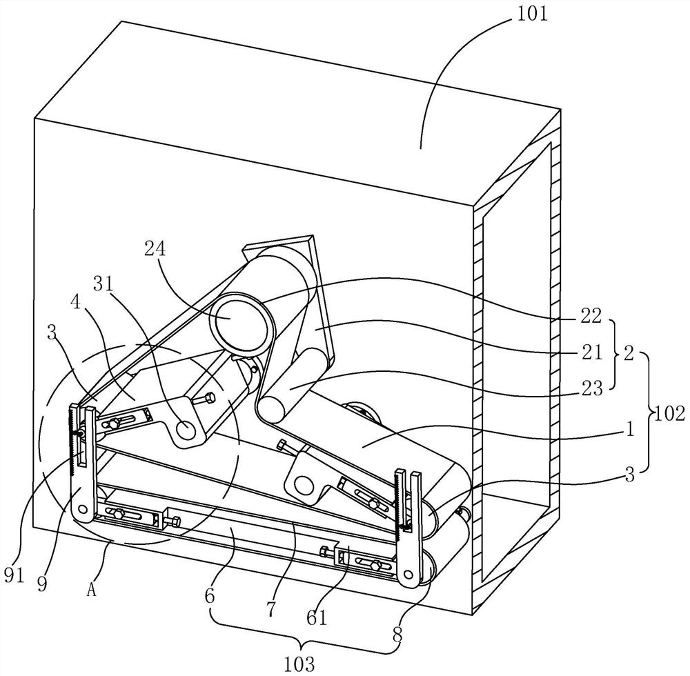
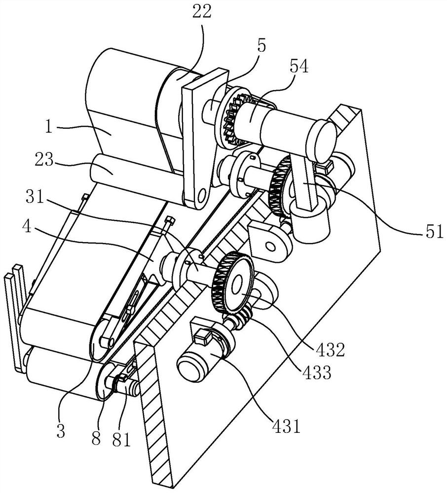
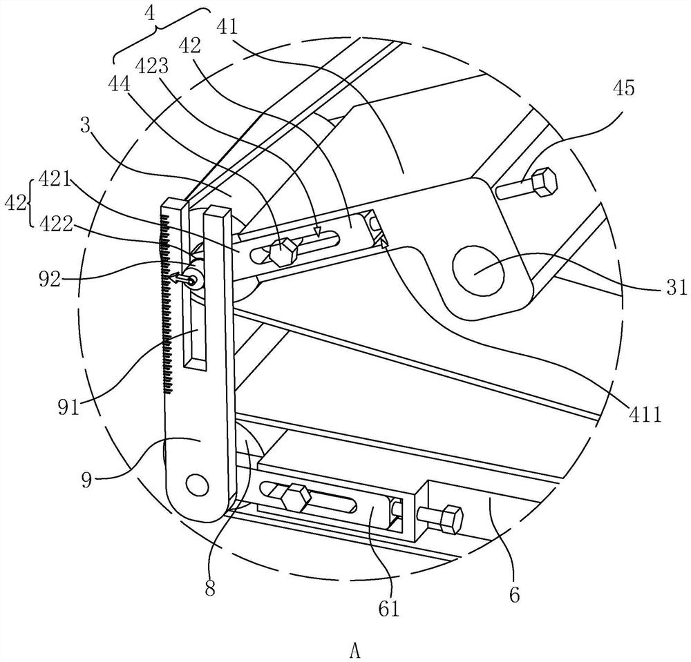
Cotton pressing and conveying mechanism and antiperspirant pad forming equipment

A conveying mechanism and cotton pressing technology, which is applied in the direction of conveyors, laminations, lamination devices, etc., can solve the problems of limited conveying effect of the conveyor belt on the cotton belt, loose cotton belt, and large change in the thickness of the cotton belt.

Active Publication Date: 2021-09-10
浙江亿维护理用品有限公司
View PDF12 Cites 1 Cited by
  • Summary
  • Abstract
  • Description
  • Claims
  • Application Information

AI Technical Summary

Problems solved by technology

With the use of the equipment, the distance between the two sets of conveyor belts may change. If the distance between the two sets of transmission belts is too large, the conveyor belt’s driving effect on the cotton belt will be limited, and the surface of the conveyor belt and the surface of the cotton belt will easily slip. The cotton belt is loose and the surface is easily torn off by the conveyor belt. If the distance between the two sets of conveyor belts is too small, the thickness of the cotton belt at the entrance of the conveyor belt may change too much, and the cotton belt loses the ability to move adaptively relative to the conveyor belt. , prone to fracture problems at the entrance

Method used


Image

  • Cotton pressing and conveying mechanism and antiperspirant pad forming equipment
  • Cotton pressing and conveying mechanism and antiperspirant pad forming equipment
  • Cotton pressing and conveying mechanism and antiperspirant pad forming equipment

Examples


Embodiment 2

[0067] Embodiment 2, with reference to Figure 6 , the difference from Embodiment 1 is that the movable seat 42 is attached to both sides of the fixed seat 41, and each side of the fixed seat 41 connected with the movable seat 42 is provided with a first stopper that is threadedly connected with the fixed seat 41 44 , the first limiting member 44 passes through the first waist hole 423 and presses the movable seat 42 to the fixed seat 41 . The moving seat 42 is provided with an arc-shaped hole 425 at one end of the first waist hole 423, and the middle part of the fixed seat 41 is provided with a cavity 426, and the side wall of the fixed seat 41 is provided with a second waist hole communicating with the cavity 426. 427, the movable seat 42 is provided with a second stopper 46, and the second stopper 46 includes a second bolt 461 and a second nut 462, wherein the second bolt 461 passes through the second waist hole 427 and the arc hole 425 , the nut of the second bolt 461 and...

Embodiment 3

[0071] Embodiment 3, an antiperspirant pad forming equipment, which uses the pressing cotton conveying mechanism of the above-mentioned embodiment 1 or embodiment 2.


PUM


Abstract

The invention relates to a cotton pressing and conveying mechanism and antiperspirant pad forming equipment. The cotton pressing and conveying mechanism comprises a machine frame and further comprises an upper conveying belt and a lower conveying belt, the upper conveying belt comprises a driving roller, a driven roller and a conveying belt, the conveying belt surrounds the driving roller and the driven roller, the driving roller is connected to the machine frame, the side wall of the machine frame is rotationally connected with a rotating shaft and a driving mechanism, the peripheral side of the rotating shaft is connected with a roller frame in a rotation-stopping mode, the driven roller is rotationally connected to the roller frame, the driving mechanism comprises a driving source, a turbine and a worm, the turbine is fixed to the rotating shaft, and the driving source drives the turbine through the worm. The cotton pressing and conveying mechanism has the advantages that the distance can be adjusted in real time according to the cotton pressing thickness requirement, and therefore the better cotton pressing effect is achieved.

Description

technical field [0001] The present application relates to the field of production equipment for daily necessities, in particular to a cotton pressing conveying mechanism and antiperspirant pad forming equipment. Background technique [0002] Antiperspirant pads are widely used in all aspects of life, such as seat cushions, insoles, saddles, underarm antiperspirant pads, etc. And no matter what kind of antiperspirant pad must include a surface layer and a cotton layer, wherein the cotton layer is enclosed between multiple surface layers. [0003] Therefore, the forming equipment of the antiperspirant pad mainly includes a cotton belt forming mechanism for making loose cotton raw materials into a belt-shaped cotton body, a cotton pressing conveying mechanism for conveying the cotton belt, and a composite mechanism for compounding the cotton layer between multiple surface layers. [0004] The pressing cotton conveying mechanism is mainly composed of two groups of conveyor belt...

Claims


Application Information

Patent Timeline
IPC IPC(8): B65H20/06B65G23/44B65G23/04B65G21/12B65G15/14B32B37/00G01B3/02
CPCB65H20/06B65G15/14B65G21/12B65G23/04B65G23/44G01B3/02B32B37/00
Inventor 詹望
Owner 浙江亿维护理用品有限公司
Learn More