Bistable double-piezoelectric cantilever beam vibration energy collector

A vibration energy harvesting and cantilever beam technology, which is applied in the direction of piezoelectric effect/electrostrictive or magnetostrictive motors, generators/motors, electrical components, etc., can solve the problem of limited energy supply time or power, and reduce electromechanical energy conversion Efficiency, limiting the miniaturization of microsensors and other issues

Inactive Publication Date: 2013-12-25
TIANJIN UNIV
View PDF3 Cites 11 Cited by
  • Summary
  • Abstract
  • Description
  • Claims
  • Application Information

AI Technical Summary

Problems solved by technology

But as we all know, the main disadvantages of this kind of battery are: first, (compared to the micro sensor) the volume is relatively large, which limits the further miniaturization of the micro sensor; second, the energy supply time or power is limited, and it needs to be replaced or charged after a period of use , especially for wireless sensors in harsh climates or remote areas, this is a very harsh constraint
When the vibration excitation intensity is insufficient, the response of the cantilever beam cannot achieve a large-amplitude bistable transition oscillation, thereby reducing the electromechanical energy conversion efficiency

Method used


Image

  • Bistable double-piezoelectric cantilever beam vibration energy collector
  • Bistable double-piezoelectric cantilever beam vibration energy collector
  • Bistable double-piezoelectric cantilever beam vibration energy collector

Examples


Embodiment Construction

[0016] The technical solutions of the present invention will be further described below with reference to the drawings and embodiments.

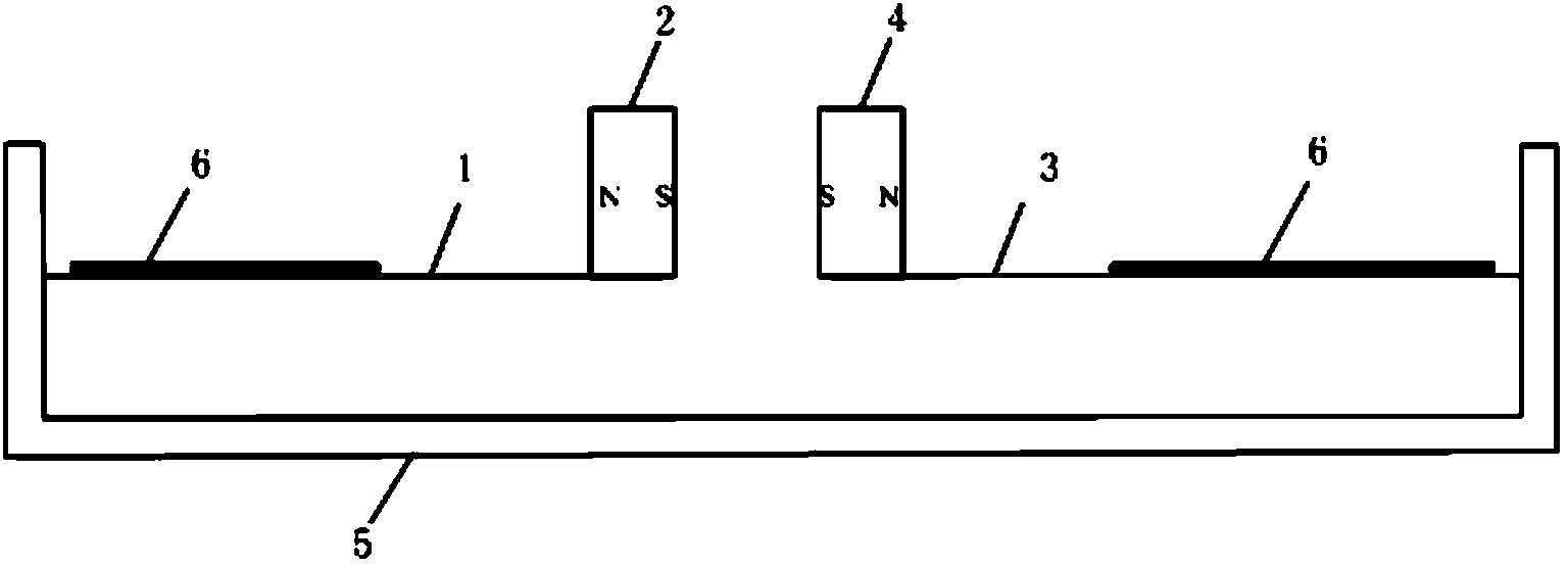
[0017] The structure of the bistable bi-stable piezoelectric cantilever beam vibration energy harvester is: two cantilever beams are placed on the same horizontal line and arranged left and right, the free end of the left cantilever beam 1 is equipped with an inner magnet 2, and the free end of the right cantilever beam 3 is installed There is an outer magnet 4, the fixed ends of the two cantilever beams are fixedly installed on the vertical surface of the right-angle base 5, and the magnetic polarities of the outer magnet and the inner magnet are oppositely arranged. Piezoelectric sheets 6 are respectively pasted on the fixed end of each cantilever beam at a position 2-3mm away from the vertical plane of the right-angle base. The vibration of the cantilever beam causes the piezoelectric sheet to generate electric energy, and the piezoelectric s...


PUM


Abstract

The invention discloses a bistable double-piezoelectric cantilever beam vibration energy collector. The bistable double-piezoelectric cantilever beam vibration energy collector is characterized in that two cantilever beams are oppositely arranged on a horizontal line in a left-and-right mode, an internal magnet is installed at the free end of the cantilever beam on the left side, an external magnet is installed at the free end of the cantilever beam on the right side, the fixed ends of the two cantilever beams are fixedly installed on the vertical plane of a right-angle base, the external magnet and the internal magnet are arranged in the mode that the magnetic polarity of the external magnet and the magnetic polarity of the internal magnet are oppositely rejected with each other, piezoelectric patches are pasted at the positions, 2-3mm away from the vertical plane of the right-angle base, of the fixed ends of the two cantilever beams, vibration of the cantilever beams enables the piezoelectric patches to generate electric energy, and the piezoelectric patches are connected with a lead to output the electric energy. Random excitation vibration is carried out on the variable environment, and the electric energy can be effectively converted through the bistable double-piezoelectric cantilever beam vibration energy collector under the condition that structure parameters are fixed and unchanged. Real-time adjustment on the distance of the magnets is required to be continuously carried out through the rigid supporting external magnet according to variation of environmental excitation strength. The bistable double-piezoelectric cantilever beam vibration energy collector is arranged beside a road and the field having the vibration excitation background, and the vibration energy can be converted into the electric energy.

Description

Technical field [0001] The invention belongs to vibration or piezoelectric energy conversion technology, and specifically relates to a bistable bi-stable piezoelectric cantilever beam that uses a piezoelectric cantilever beam to support an external magnet, and a device for collecting and generating vibration energy. Background technique [0002] In recent years, with the development of microelectronics and radio wave technology, handheld electronic devices and wireless sensors have entered an era of miniaturization and low power consumption. Under normal circumstances, these devices rely on traditional batteries to provide energy, such as nickel-metal hydride batteries, lithium polymer batteries and so on. However, as we all know, the main shortcomings of this kind of battery are: First, (compared to the micro sensor) is relatively large, which limits the further miniaturization of the micro sensor; Second, the energy supply time or power is limited, and it needs to be replaced o...

Claims


Application Information

Patent Timeline
Patent Type & Authority Applications(China)
IPC IPC(8): H02N2/18
Inventor 冷永刚高毓璣范胜波赖志慧郭焱
Owner TIANJIN UNIV
Why Eureka
Try Eureka