
Bridge swivel system and mounting and swivel method thereof

An installation method and a swivel technology, applied in bridges, bridge construction, bridge parts, etc., can solve problems such as short cycle and inability to construct

Pending Publication Date: 2021-09-10
WUHAN YIYE CONSTR ENG
View PDF7 Cites 2 Cited by
  • Summary
  • Abstract
  • Description
  • Claims
  • Application Information

AI Technical Summary

Problems solved by technology

[0003] The purpose of the present invention is to provide a bridge swivel system and its installation and swivel method, which can realize the bridge swivel, ensure the stability and safety of the swivel, operate safely, have high efficiency, and have a short period, and can solve the problem that the existing viaduct spans two The problem that the railway line cannot be constructed

Method used


Image

  • Bridge swivel system and mounting and swivel method thereof
  • Bridge swivel system and mounting and swivel method thereof
  • Bridge swivel system and mounting and swivel method thereof

Examples


Embodiment Construction

[0031] The present invention will be further described below in conjunction with the accompanying drawings and embodiments.

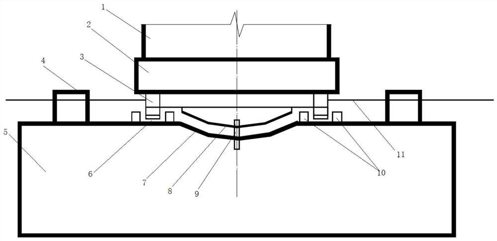
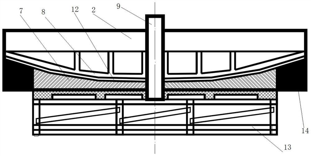
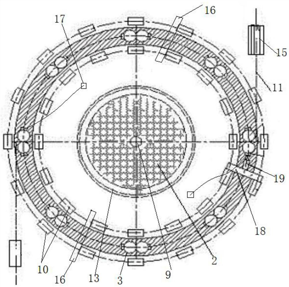
[0032] Such as Figure 1 to Figure 3 As shown, a bridge swivel system includes a swivel device and a traction device; the swivel device includes an upper turntable 2 arranged at the bottom of the pier 1, an upper spherical hinge 8 and a leg 3 arranged at the bottom of the upper turntable 2, and a pre-buried on the bearing The lower turntable 14 and the slideway 6 at the top of the table 5, the lower ball joint 7 at the top of the lower turntable 14, the positioning shaft 9 at the center of the lower ball joint 7, the upper ball joint 8 and the lower ball joint 7 are closely fitted as the main support and There is a sliding plate 12 between the two, the upper turntable 2 and the upper ball joint 8 are positioned by the positioning shaft 9, and the outrigger 3 and the slideway 6 are used as auxiliary supports for sliding fit; the traction device includes ...


PUM


Abstract

The invention discloses a bridge swivel system and a mounting and swivel method thereof. A swivel device comprises an upper turntable arranged at the bottom of a bridge pier, an upper spherical hinge and a supporting leg which are arranged at the bottom of the upper turntable, a lower turntable and a slideway which are pre-buried at the top of a bearing platform, a lower spherical hinge arranged at the top of the lower turntable, and a positioning shaft arranged at the center of the lower spherical hinge; the upper spherical hinge and the lower spherical hinge serve as main supports and are in close fit, a sliding piece is arranged between the upper spherical hinge and the lower spherical hinge, and the upper rotary disc and the upper spherical hinge are positioned through a positioning shaft. The supporting leg and the slideway serve as assisted supports and are in sliding fit. The traction device comprises an anchor bearing and a prestress channel which are pre-buried on the upper turntable, a steel strand of which one end penetrates through the prestress channel and is connected with the anchor bearing, traction jacks connected with the other end of the steel strand, and a traction counter-force seat, a boosting counter-force seat and a limiting structure which are arranged at the top of the bearing platform; and the two groups of traction jacks and steel strands are reversely arranged on two sides of the upper turntable and can be controlled to be synchronous. The system is stable and safe in rotation, high in efficiency and capable of crossing two railway lines.

Description

technical field [0001] The invention belongs to the field of viaduct bridge construction, and in particular relates to a bridge swivel system and its installation and swivel methods. Background technique [0002] Bridge swivel construction is widely used in bridge projects such as high mountains and canyons, urban overpasses, railway crossings, etc. Bridge swivel construction is to transform the construction of the upper part of the obstacle into shore or near-ground construction. The bridge is divided into two half-spans with the mid-span as the boundary line, and the swivel system is used to rotate the two half-spans respectively and close them at the mid-span. The current bridge swivel system has low swivel efficiency and cannot cross two railway lines. Contents of the invention [0003] The purpose of the present invention is to provide a bridge swivel system and its installation and swivel method, which can realize the bridge swivel, ensure the stability and safety o...

Claims


Application Information

Patent Timeline
IPC IPC(8): E01D21/08E01D19/02E01D19/00
CPCE01D21/08E01D19/02E01D19/00
Inventor 黄轶张婷婷赵海莲
Owner WUHAN YIYE CONSTR ENG
Learn More