Coupling signal transmitting device

A technology for transmitting devices and coupling signals, which is applied in the direction of measuring devices, measuring device casings, instruments, etc., and can solve the problems of magnetic cores affecting test accuracy and effectiveness

Active Publication Date: 2021-09-10
深圳潜宇科技有限公司
View PDF10 Cites 0 Cited by
  • Summary
  • Abstract
  • Description
  • Claims
  • Application Information

AI Technical Summary

Problems solved by technology

[0007] In order to solve the technical problems raised by the background technology, the present invention provides a coupling signal transmitting device, which can effectively solve the problem that the accuracy and effectiveness of the test are affected by the impact deformation of the magnetic core and the leakage of the magnetic induction line.

Method used


Image

  • Coupling signal transmitting device
  • Coupling signal transmitting device
  • Coupling signal transmitting device

Examples


Embodiment Construction

[0040] The specific embodiments provided by the present invention will be described in detail below in conjunction with the accompanying drawings.

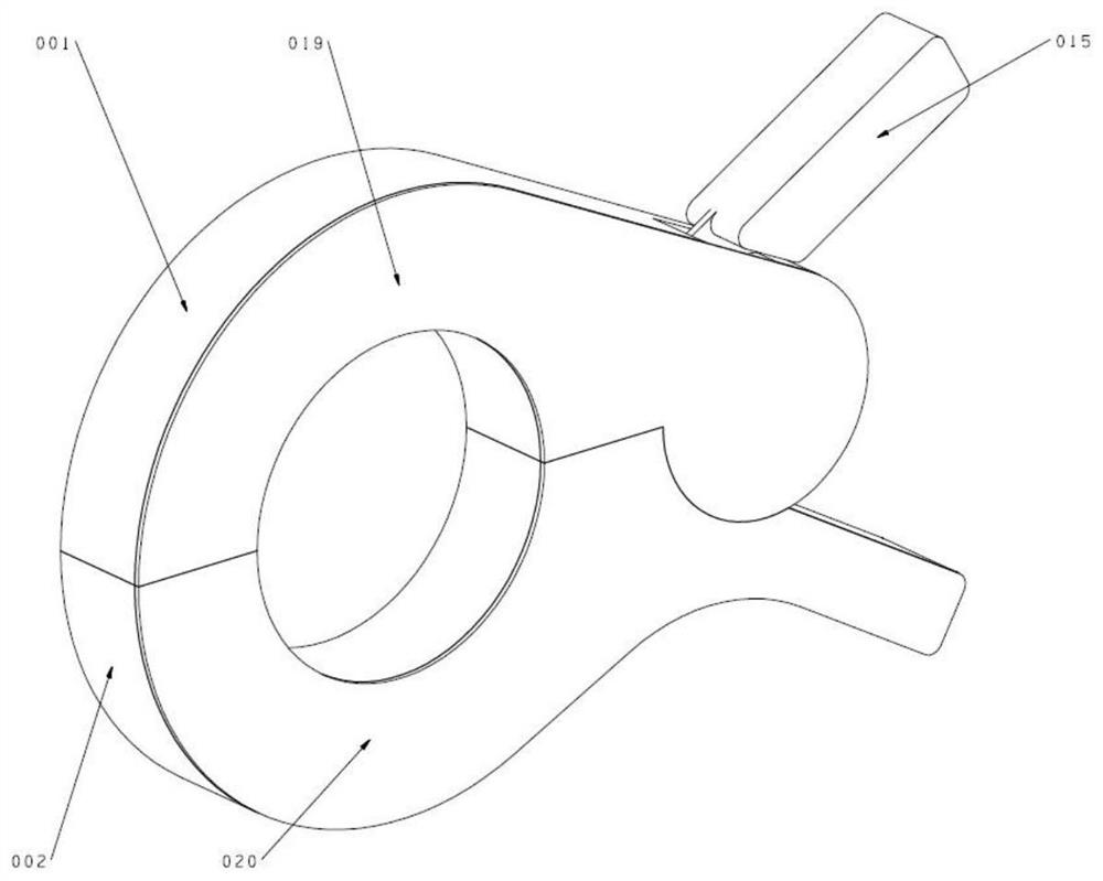
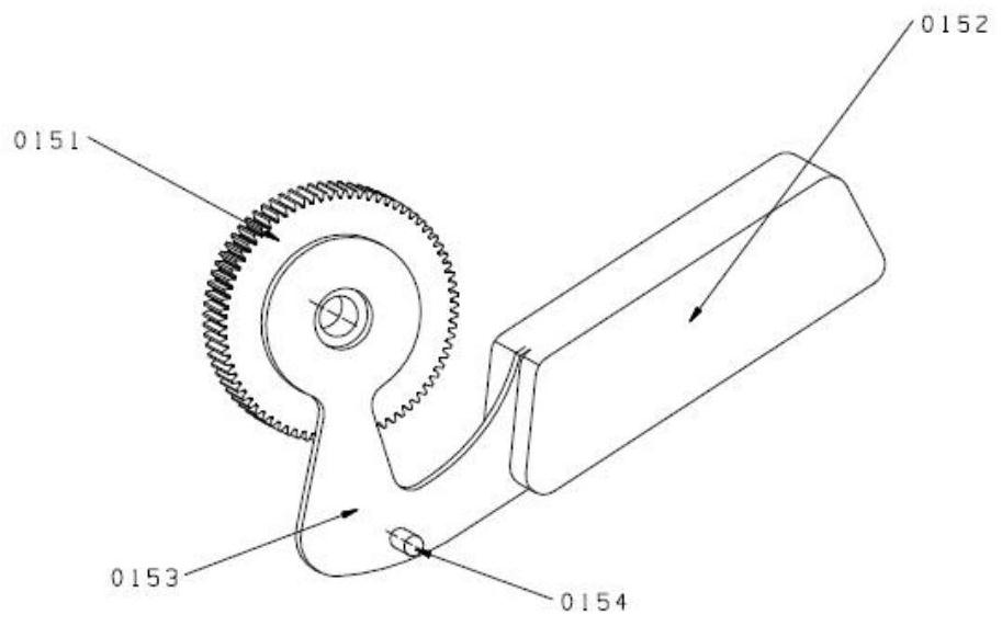
[0041] Such as Figure 1-9As shown, a coupling signal transmitting device includes a handleless upper clamp device (housing 1), a handle lower clamp device (housing 2) and a driving gear device 15 with a handle, and a handleless upper clamp device (housing 1 ) and the lower pincer device with handle (housing 2) are semicircular structures, the driving gear device 15 with handle is fixed on the tail of the upper pincer device without handle (housing 1), and the upper pincer device without handle (housing 1) Combined with the afterbody of the band handle lower pincers (housing 2) by the positioning pins 18 and the positioning tables of the two shells.

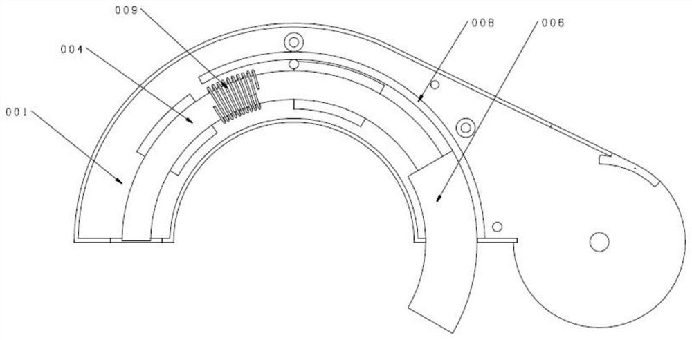
[0042] See figure 2 , the handleless upper pincer device (housing 1) includes the handleless pincer shell 1, the upper half magnetic core 4, the excitation coil-9, the upper magne...


PUM


Abstract

The invention provides a coupling signal transmitting device, which comprises a handle-free upper pincerlike device, a handle-equipped lower pincerlike device and a handle-equipped driving gear device, wherein the handle-free upper pincerlike device and the handle-equipped lower pincerlike device are both semicircular structures, the handle-equipped driving gear device is fixed at the tail part of the handle-free upper pincerlike device, and the tail parts of the handle-free upper pincerlike device and the handle-equipped lower pincerlike device are combined together through a positioning pin and the positioning table surfaces of the two shells. The handle-free upper pincerlike device comprises a handle-free pincerlike shell, an upper half magnetic core, a first magnet exciting coil, an upper magnetic sleeve and an upper stroke guide rail; and the handle-equipped lower pincerlike device comprises a pincerlike shell with the handle, a lower half magnetic core, a second magnet exciting coil, a lower magnetic conductive sleeve and a lower stroke guide rail. The problem that the test accuracy and effectiveness are influenced by impact deformation and magnetic induction line leakage of the magnetic core can be effectively solved.

Description

technical field [0001] The invention relates to the technical field of power system devices, in particular to a coupling signal transmitting device. Background technique [0002] At present, with the development of the city, the overhead line can no longer meet the power supply demand of the power system for the city, and the underground cable has the characteristics of concealment and safety, and has already dominated the urban power supply network. [0003] As the number of underground cables increases, the number of faults also increases, often requiring a lot of work such as path query and cable identification. [0004] For the live cable, since the core part of the cable cannot be directly contacted, the coupling method is usually used to couple the signal to the inside of the cable, and the entire cable has a coupled input test signal, so as to complete the path query and cable identification. [0005] The most commonly used coupling for transmitting signals is a clam...

Claims


Application Information

Patent Timeline
Patent Type & Authority Applications(China)
IPC IPC(8): G01R1/04G01R1/28
CPCG01R1/0416G01R1/28Y02E60/00
Inventor 许志香
Owner 深圳潜宇科技有限公司
Why Eureka
Try Eureka