Tower crane emergency escape self-rescue knapsack type slow descent device and application method thereof
A backpack-style, emergency technology, applied in the field of escape backpack slow down, can solve the problems of automatic and manual locking, affecting the life safety of users, poor safety and protection performance, etc.
- Summary
- Abstract
- Description
- Claims
- Application Information
AI Technical Summary
Problems solved by technology
Method used
Image
Examples
Embodiment 1
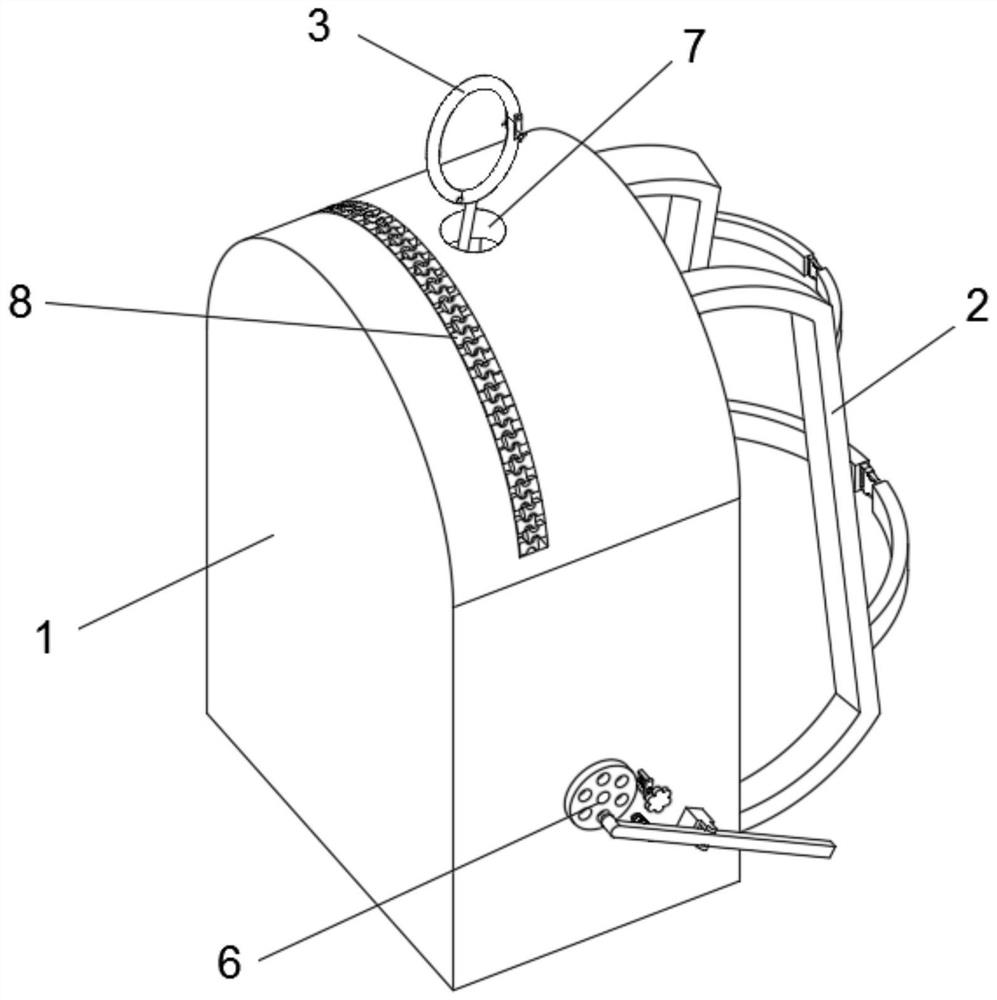
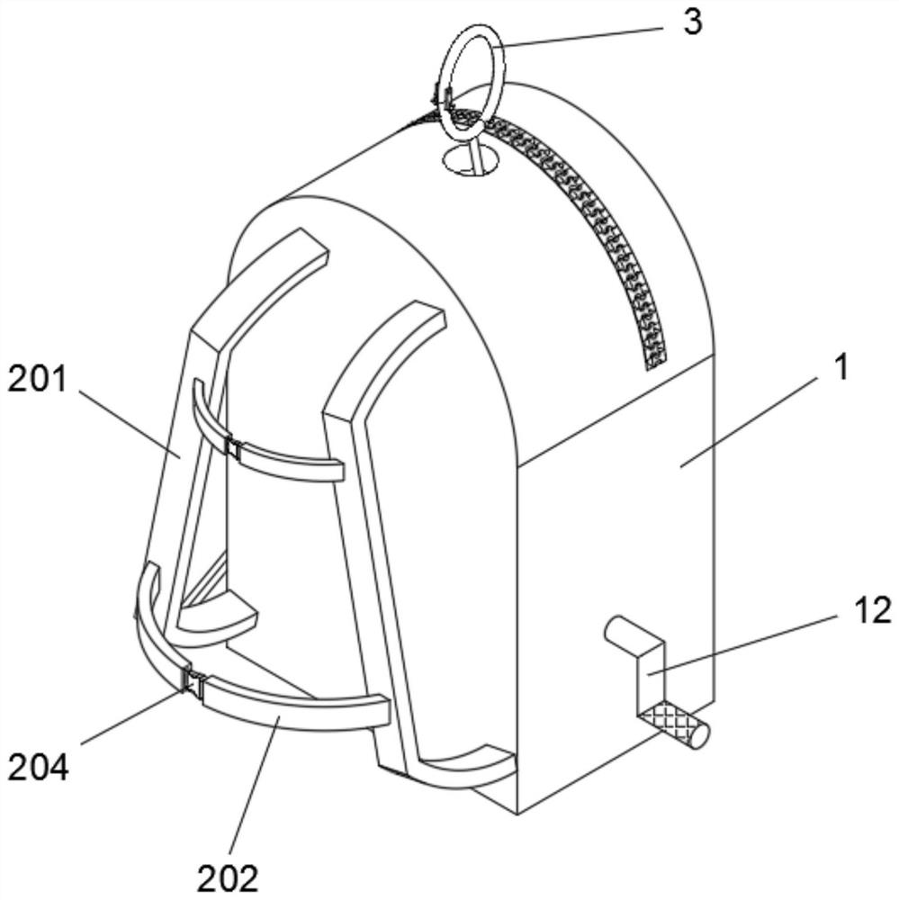
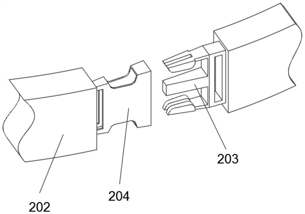
[0039] like Figure 1-6 , The crane emergency escape self backpack Descent apparatus main body 1 comprises a backpack, the backpack body 1 is provided with a rear end tightening assembly 2, the backpack body 1 is provided with an upper end hung assembly 3, inside the lower end of the backpack body 1 is provided with a winch 4 , ramp down winch assembly 4 is provided with a right end 5, right end of the winch 4 is provided with locking assembly 6, comprises two tightening strap assembly 201, straps 201 form two symmetrical structure is provided, a rear backpack body goes symmetric structure is fixed there are two tightening band 202, 202 with the central tightening chuck 203 is provided with left, middle right tightening band 202 is provided with a snap-204.
[0040] 4 have winding winch ropes 9, the winch 4 is mounted a central shaft 10, a shaft 10 rotatably connected to the backpack body, the chuck 203 and the snap 204 snap fit, a surface of the backpack body defines a through hol...
Embodiment 2
[0044] like Figure 7 , Figure 8 , In the embodiment 1 on the basis of embodiments, ramping down assembly 5 comprises an upper disc notch 501, slit disk 501 into frictional contact with a rear sheave 502, a left end 501 fixed slit disk has a fixed lever 503, lever 503 fixed to a right wall provided with a solid cylindrical pins 504, 502 form a sheave array structure defines a radial annular groove 505, the right end of the central sheave 502 is fixedly disposed sleeve A506, A506 sheave casing 502 and the central rod 507 is provided with a solid , the right end of the slide rod 507 is connected with a sleeve B508, B508 arranged one above the sleeve is provided with two symmetrical structure fixed slider 509.
[0045] 505 slidable cylindrical pin 504 is connected with the radial grooves, notches 501 and the disc wheel groove connecting the recess 502 of the slide sleeve A506 B508 right wall and left wall of the sleeve has teeth, the teeth of the cannula through the right A506 B508 le...
Embodiment 3
[0048] like Figure 9 , Figure 10 , In the embodiment 2 based on the embodiment, the locking assembly includes a ratchet 6 turns 601, a left wall 601 with the ratchet ring inside right wall connected to the backpack body 1 is fixed, the internal ratchet ring 601 is provided with a round block 602, the front surface of the knobs 602 the upper end of the cylinder 603 is fixedly disposed, rotatably connected to the pawl 604 on the cylinder 603, the lower end of the right side of the pawl 604 a spring fixing A605, A605 right end of the spring is connected by the connection block 606 is fixed to the round block 602, rotation of the ratchet ring 10 and the shaft 601 connections, the connection cylinder 603 and fixed shaft 10, the pawl 604 with the ratchet ring 601 snap fit.
[0049] Further comprising a backpack body located in a lower right end stop assembly 11, assembly stop 11, stop plate assembly 11 includes a stop 1101, as a stop disc positioning holes 1101 of the right wall structu...
PUM
 Abstract
Description
Claims
Application Information
 - R&D
- Intellectual Property
- Life Sciences
- Materials
- Tech Scout
- Unparalleled Data Quality
- Higher Quality Content
- 60% Fewer Hallucinations
Browse by: Latest US Patents, China's latest patents, Technical Efficacy Thesaurus, Application Domain, Technology Topic, Popular Technical Reports.
© 2025 PatSnap. All rights reserved.Legal|Privacy policy|Modern Slavery Act Transparency Statement|Sitemap|About US| Contact US: help@patsnap.com


