
Intelligent cleaning line for locomotives

An intelligent cleaning and locomotive technology, applied in the field of robotics, can solve the problems of heavy weight, large stroke, short service life and other problems

Pending Publication Date: 2021-09-14
北京炎凌嘉业机电设备有限公司
View PDF0 Cites 0 Cited by
  • Summary
  • Abstract
  • Description
  • Claims
  • Application Information

AI Technical Summary

Problems solved by technology

[0003] Defects and deficiencies in the prior art: the shape of modern locomotives is mostly designed as a full arc shape in order to reduce air resistance and aesthetic effect
[0005] 2. When the cylinder sealing ring and guide sleeve are aging, the cylinder will appear crawling phenomenon, especially the position of the cylinder in the existing locomotive cleaning line is placed horizontally, and the stroke is large, and its own weight is large, causing the middle of the cylinder to sag. Sticking and crawling are particularly severe
The cylinder works in a humid environment for a long time, and its service life is short
[0006] 3. The long-axis roller brush can only perform rough cleaning on a large area of ​​the locomotive
The protruding part of the locomotive arc has overwashing phenomenon, which will cause serious damage to the paint surface
And the sunken parts of the locomotive can't be cleaned
[0007] 4. The locomotive cleaning line currently in use requires a lot of manual cleaning for the front face, large curved surface, doors, windows, etc. of the cleaned locomotive

Method used


Image

  • Intelligent cleaning line for locomotives
  • Intelligent cleaning line for locomotives
  • Intelligent cleaning line for locomotives

Examples


Embodiment Construction

[0036] The technical solutions of the present invention will be further specifically described below through specific embodiments and in conjunction with the accompanying drawings.

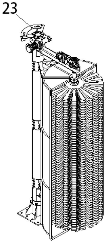
[0037] Such as Figure 1 to Figure 13 As shown, the intelligent cleaning line for locomotives includes the locomotive track, the car entrance arranged at the left end of the locomotive track, the left parking sign and light 15, the locomotive deceleration indicator light and the sign 14, which are arranged in turn from the car entrance to the right end of the locomotive track. Locomotive flushing and leak detection station 13, locomotive washing station 12, locomotive drying station 11, locomotive spraying station 10, locomotive side fine brushing station 9, locomotive side arc top fine brushing station 8, locomotive side washing worker Position 7, Locomotive side rough brushing position 6, Locomotive side arc top rough brushing position 5, Locomotive door and window scrubbing position 4, Locomoti...


PUM


Abstract

The invention relates to the field of robots, in particular to an intelligent cleaning line for locomotives. The cleaning line comprises a locomotive track, a locomotive inlet arranged at the left end part of the locomotive track, a left parking signboard and a lamp which are sequentially arranged from the locomotive inlet to the right end of the locomotive track, a locomotive deceleration indicating lamp and board, a locomotive washing leakage detection station, a locomotive washing station, a locomotive drying station, a locomotive spraying station, a locomotive side surface fine brushing station, a locomotive side arc top fine brushing station, a locomotive side washing station, a locomotive side rough brushing station, a locomotive side arc top rough brushing station, a locomotive door and window brushing station, a locomotive top rough brushing station, a locomotive face cleaning station, a right parking space signboard and a lamp. The invention aims to apply stable pressure to a rolling brush by using a reliable servo control machine on the basis of fully researching the cleaning process requirements, carry out all-directional profiling intelligent cleaning on a locomotive by using an electronic intelligent technology, and carry out profiling cleaning on the front and rear arc-shaped surfaces of the locomotive and the sunken part of a vehicle door by using manipulators on the basis of fully researching the cleaning process requirements.

Description

technical field [0001] The invention relates to the field of robots, and more specifically, relates to an intelligent cleaning line for locomotives. Background technique [0002] The current locomotive cleaning machines in use all use cylinders to drive the roller brush frame to approach the locomotive, and use the thrust of the cylinder to clean the front and rear faces and sides of the locomotive with brushing in large areas. The distance and thrust of the roller brush from the vehicle body are all accomplished by the air pressure of the cylinder. [0003] Defects and deficiencies of the prior art: the shape of modern locomotives is mostly designed into a full arc shape in order to reduce air resistance and aesthetic effect. There are local dents in the door and other places. And existing cleaning machine, the mode that rolling brush is close to locomotive all utilizes cylinder to promote, and the defective of this cleaning method is as follows. [0004] 1. The thrust o...

Claims


Application Information

Patent Timeline
IPC IPC(8): B60S3/04
CPCB60S3/04
Inventor 杨海峰孙俊达刘林魁高峰闫双喜
Owner 北京炎凌嘉业机电设备有限公司
Learn More