
Laser radar rotary reflection device and laser radar

A technology of laser radar and rotating reflection, which is applied in the direction of radio wave measurement systems and instruments, can solve the problems of insufficient scanning accuracy, large vibration of mirrors, and difficulty in meeting high standards of bearing coaxiality.

Pending Publication Date: 2021-09-14
NINGBO ONSIGHT CO LTD
View PDF10 Cites 0 Cited by
  • Summary
  • Abstract
  • Description
  • Claims
  • Application Information

AI Technical Summary

Problems solved by technology

This fixing method makes it difficult for the coaxiality of the bearings at both ends of the mirror to reach a high standard. When the rotating structure drives the mirror to rotate and scan, the mirror will generate large vibrations, resulting in insufficient scanning accuracy.

Method used


Image

  • Laser radar rotary reflection device and laser radar
  • Laser radar rotary reflection device and laser radar
  • Laser radar rotary reflection device and laser radar

Examples


Embodiment Construction

[0025] The technical solutions in the embodiments of the present application will be clearly and completely described below with reference to the drawings in the embodiments of the present application. Obviously, the described embodiments are only a part of the embodiments of the present application, but not all of the embodiments. Based on the embodiments in the present application, all other embodiments obtained by those of ordinary skill in the art without creative efforts shall fall within the protection scope of the present application.

[0026] The terms "first", "second" and "third" in this application are only used for descriptive purposes, and should not be construed as indicating or implying relative importance or implying the number of indicated technical features. Thus, a feature defined as "first", "second", "third" may expressly or implicitly include at least one of that feature. In the description of the present application, "a plurality of" means at least two, ...


PUM


Abstract

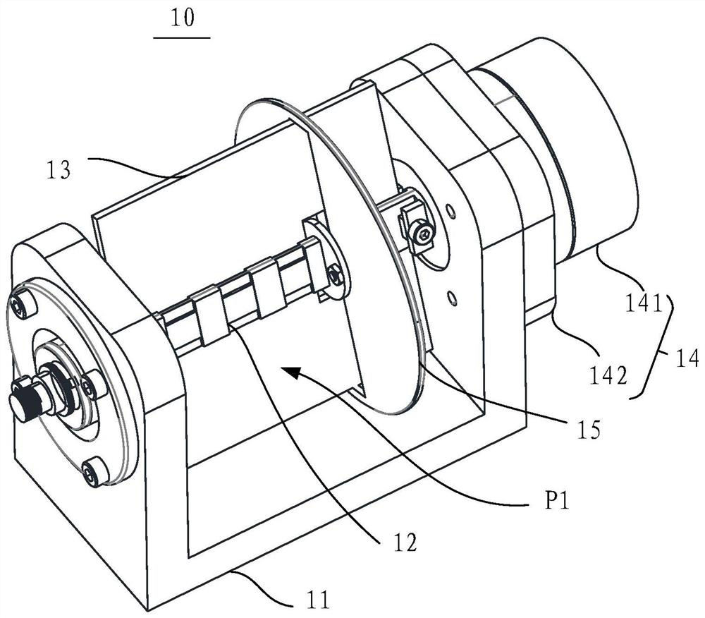
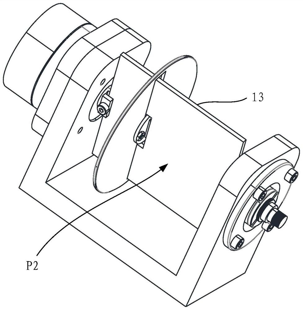
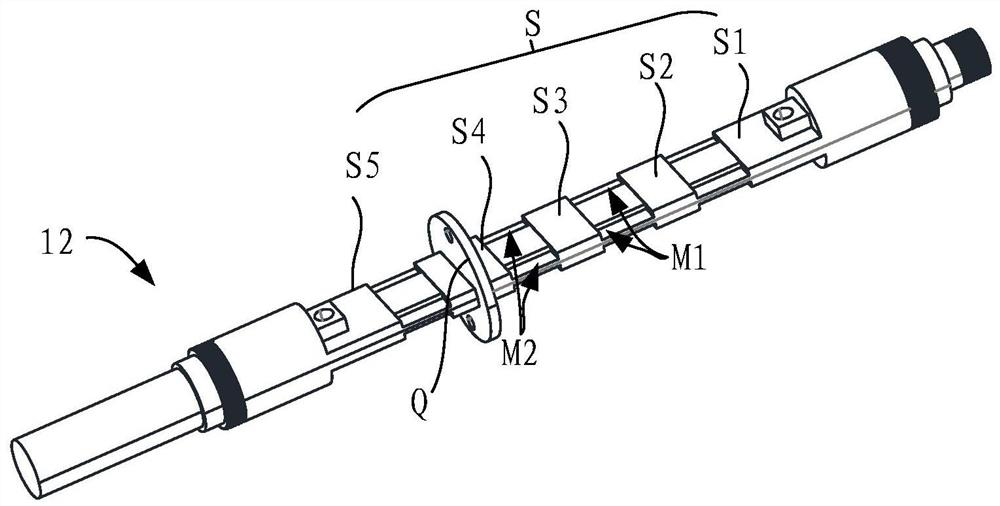
The invention discloses a laser radar rotation reflection device. The device comprises: a supporting assembly; a rotating shaft, wherein the two ends of the rotating shaft are supported on the supporting assembly, and the rotating shaft is provided with a positioning part; a reflecting mirror which is arranged on the positioning part and is provided with a reflecting surface, wherein the reflecting surface is used for reflecting the laser beam; and a driving assembly which is used for driving the rotating shaft to rotate so that the reflecting mirror can rotationally reflect the laser beam. Therefore, the reflecting mirror of the laser radar rotary reflecting device is fixed on the positioning part of the rotating shaft, the reflecting mirror can rotate around the only rotating shaft, the coaxiality of the bearings at the two ends of the reflecting mirror is improved, and then the scanning precision is improved.

Description

technical field [0001] The present application relates to the technical field of lidar, and in particular, to a lidar rotating reflection device and a lidar. Background technique [0002] LiDAR (LightLaser Detection and Ranging), the abbreviation of Laser Detection and Ranging System, is a radar that uses a laser emitting component as a radiation source. In the process of detection by lidar, the lidar irradiates the object with the emission beam emitted by the laser emitting component, causing scattering, and a part of the beam forms a receiving beam and is received by the laser receiving component of the lidar. According to the beam received by the laser receiving component, information such as the distance from the lidar to the object and the specific shape of the object can be obtained. [0003] The mirror is applied to the lidar, and the mirror is fixed by the rotating structure, so that the mirror is driven by the rotating structure to rotate and reflect the laser beam...

Claims


Application Information

Patent Timeline
Patent Type & Authority Applications(China)
IPC IPC(8): G01S7/481
CPCG01S7/481G01S7/4817
Inventor 李志
Owner NINGBO ONSIGHT CO LTD
Learn More