Electromagnetic driving device and microwave switch

An electromagnetic drive, microwave channel technology, applied to the power devices, circuits, electrical components and other directions inside the switch, which can solve the problems of interference, large size, and large magnetic field leakage of surrounding magnetic sensitive equipment.

Pending Publication Date: 2021-09-14
美迅无锡通信科技有限公司
View PDF0 Cites 0 Cited by
  • Summary
  • Abstract
  • Description
  • Claims
  • Application Information

AI Technical Summary

Problems solved by technology

[0004] 1) The leakage of the magnetic field is large, which is easy to cause interference to the surrounding magnetic sensitive equipment;
[0005] 2) The utilization rate of magnetic energy is low, the volume of permanent magnet material required to achieve the same holding force or driving force is larger, and the energy consumption of the driving coil is greater;
[0006] 3) The size is large, and it is a horizontally expandable structure, which is not conducive to the miniaturization of multi-throw products

Method used


Image

  • Electromagnetic driving device and microwave switch
  • Electromagnetic driving device and microwave switch

Examples


Embodiment Construction

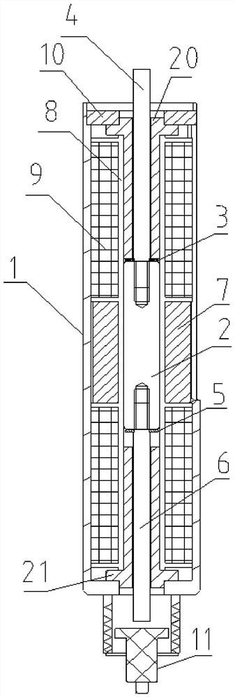
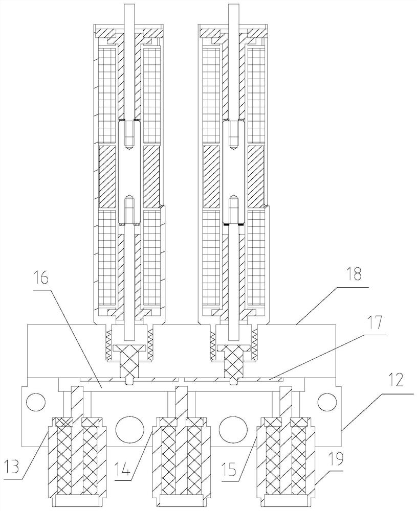
[0026] Illustrative embodiments of the present application include, but are not limited to, an electromagnetic drive and microwave switch.

[0027] Reference will now be made in detail to the exemplary embodiments, examples of which are illustrated in the accompanying drawings. When the following description refers to the accompanying drawings, the same numerals in different drawings refer to the same or similar elements unless otherwise indicated. The implementations described in the following exemplary embodiments do not represent all implementations consistent with this application. Rather, they are merely examples of apparatuses and methods consistent with aspects of the present application as recited in the appended claims.

[0028] The terminology used in this application is for the purpose of describing particular embodiments only, and is not intended to limit the application. As used in this application and the appended claims, the singular forms "a", "the", and "the...


PUM


Abstract

The invention relates to the technical field of microwave switches, and discloses an electromagnetic driving device and a microwave switch, the electromagnetic driving device comprises a sleeve, an iron core assembly is arranged in the sleeve, and the iron core assembly comprises a movable iron core, an upper static iron core arranged above the movable iron core and a lower static iron core arranged below the movable iron core; magnetic steel is arranged on the periphery of the movable iron core in the sleeve, and the movable iron core penetrates through the magnetic steel; the upper end of the movable iron core is provided with an upper magnetism isolating gasket and an upper guide rod, the upper guide rod penetrates through the upper static iron core, the lower end of the movable iron core is provided with a lower magnetism isolating gasket and a lower guide rod, the lower guide rod penetrates through the lower static iron core, the periphery of the upper static iron core is sleeved with an upper coil assembly, and the periphery of the lower static iron core is sleeved with a lower coil assembly. In actual use, power does not need to be supplied to the coil all the time to keep the microwave channel of the microwave switch in a working state, and the power consumption of the electromagnetic driving device and the microwave switch in use can be reduced.

Description

technical field [0001] The invention relates to the technical field of microwave switches, in particular to an electromagnetic drive device and a microwave switch. Background technique [0002] Microwave switches are commonly used devices for channel switching in the field of mobile communications. Microwave switches can be divided into electromechanical switches and solid-state switches according to the working principle. Electromechanical switches rely on the movement of mechanical parts to realize the conduction and shutdown of signal channels. Solid-state switches can be divided into FET and PIN diodes according to the different switching components used. category. [0003] The channel switching in the electromechanical switch is mostly realized by the attraction of the coil and the electromagnet, that is, the magnetic field is generated by energizing the coil, and the magnetic field will attract the electromagnet to move up and down. When the transmission part capable ...

Claims


Application Information

Patent Timeline
Patent Type & Authority Applications(China)
IPC IPC(8): H01P1/11H01H3/28
CPCH01P1/11H01H3/28
Inventor 王书见
Owner 美迅无锡通信科技有限公司
Why Eureka
Try Eureka