Power distribution switchgear with high safety performance

A technology of safety performance and power distribution switch, which is applied in substation/switch layout details, cooling/ventilation of substation/switchgear, substation/power distribution device shell, etc. Problems such as heat dissipation of bundled wires and cables

Pending Publication Date: 2021-09-14
江苏大师兄电气设备有限公司
View PDF0 Cites 4 Cited by
  • Summary
  • Abstract
  • Description
  • Claims
  • Application Information

AI Technical Summary

Problems solved by technology

Because there are many electrical components inside the power distribution cabinet, it will generate a lot of heat when it is working. When the heat accumulates too much, it is not conducive to the normal operation of the power distribution cabinet.
[0003] In the prior art, in order to prevent a large amount of heat stored in the cabinet from dissipating, cooling fans are generally installed on the end walls of the cabinet to dissipate heat. The wiring system, that is, for wires and cables, the installation space is narrow, if the installation is too messy, it is not conducive to dissipate the heat from the bundled wires and cables
[0004] Especially for the wiring system close to the switch components, because the switch components themselves will generate heat sources, when the heat dissipation of the two installations is poor, it is easy to accumulate heat inside, and the internal heat is too high to easily cause short-circuit spontaneous combustion of the internal components. Spontaneous combustion generally occurs under continuous high temperature conditions. If the heat is not dissipated in time, spontaneous combustion is likely to occur

Method used


Image

  • Power distribution switchgear with high safety performance
  • Power distribution switchgear with high safety performance
  • Power distribution switchgear with high safety performance

Examples


Embodiment 1

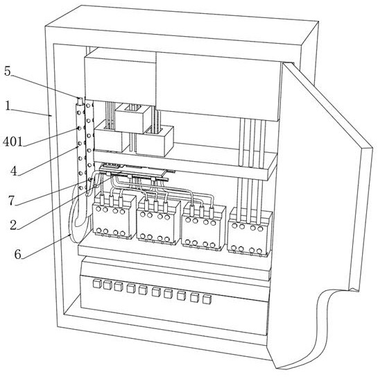
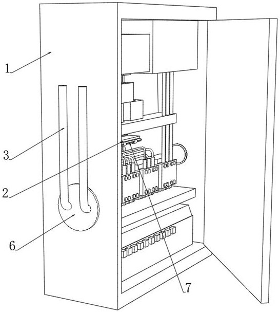
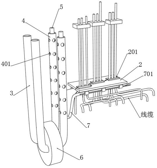
[0045] see Figure 1-4 , a power distribution switch cabinet with high safety performance, including a cabinet body 1, a switch assembly is installed in the cabinet body 1, the switch assembly and other electrical components are connected by cables, and a pair of switches are embedded on the inner wall of the cabinet body 1 The cable cladding plate 2 for positioning the component cables, the cable cladding plate 2 is provided with multiple sets of sheaths 201, and the sheath 201 is provided with a plurality of sleeve holes 2011, and the cable cladding plate 2 is separated in half along the horizontal direction of the sheath 201. There are two butt joints at the front and back, and an adhesive layer is provided at the junction of the two butt joints, which is easy to install and position multiple bundles of cables, and plays a role in combing the cables, which is conducive to the circulation of airflow and improves heat dissipation. Two butt joints that are separated front and ...


PUM


Abstract

The invention discloses a power distribution switchgear with high safety performance, and belongs to the technical field of power distribution switchgears, an outer water cooling pipe is communicated with an inner heat conduction pipe to realize large-range ventilation and heat conduction operation in a cabinet body, a first source extinguishing pipe is arranged on the inner side of the inner heat conduction pipe, and the bottom end part of the first source extinguishing pipe is connected with a second source extinguishing pipe extending to the upper part of a switch assembly. When abnormal high temperature or spontaneous combustion occurs at the switch assembly, the ventilating fan is automatically switched off, an air inlet source is blocked, then a plurality of hot melting strips on the second source extinguishing pipe are subjected to hot melting, the fire extinguishing agent in the second source extinguishing pipe overflows, and meanwhile a bearing piston is separated from the top of the first source extinguishing pipe due to the fact that the top loses magnetism due to the influence of high temperature; the bearing piston falls under the action of gravity to press source extinguishing gas in the first source extinguishing pipe into the second source extinguishing pipe, the fire extinguishing agent in the second source extinguishing pipe is driven to be sprayed out to cover the switch assembly and the cable, the source extinguishing gas and the fire extinguishing agent are matched with each other, the source extinguishing area is enlarged, and the source extinguishing effect is improved.

Description

technical field [0001] The invention relates to the technical field of power distribution switchgear, and more specifically, relates to a power distribution switchgear with high safety performance. Background technique [0002] The power distribution cabinet is the final equipment of the power distribution system. The power distribution cabinet is used in the occasions where the load is relatively scattered and the circuit is small. It distributes the electric energy of a certain circuit of the upper-level power distribution equipment to the nearest load. Since there are many electrical components inside the power distribution cabinet, it will generate a lot of heat during operation. When the heat accumulates too much, it is not conducive to the normal operation of the power distribution cabinet. [0003] In the prior art, in order to prevent a large amount of heat stored in the cabinet from dissipating, cooling fans are generally installed on the end walls of the cabinet t...

Claims


Application Information

Patent Timeline
Patent Type & Authority Applications(China)
IPC IPC(8): H02B1/28A62C3/16A62C35/10A62C35/02B01D53/26H02B1/32H02B1/20H02B1/56
CPCH02B1/28A62C3/16A62C35/10A62C35/023B01D53/261B01D53/268H02B1/32H02B1/20H02B1/565
Inventor 黄楠悦
Owner 江苏大师兄电气设备有限公司
Why Eureka
Try Eureka