Vibration isolating device
An anti-vibration device and anti-vibration technology, which is applied in the direction of power plant, jet propulsion device, internal combustion propulsion device, etc., can solve the problems that the source of vibration cannot be combined with anti-vibration performance, durability of elastic parts, etc.
- Summary
- Abstract
- Description
- Claims
- Application Information
AI Technical Summary
Problems solved by technology
Method used
Image

Examples
no. 1 approach
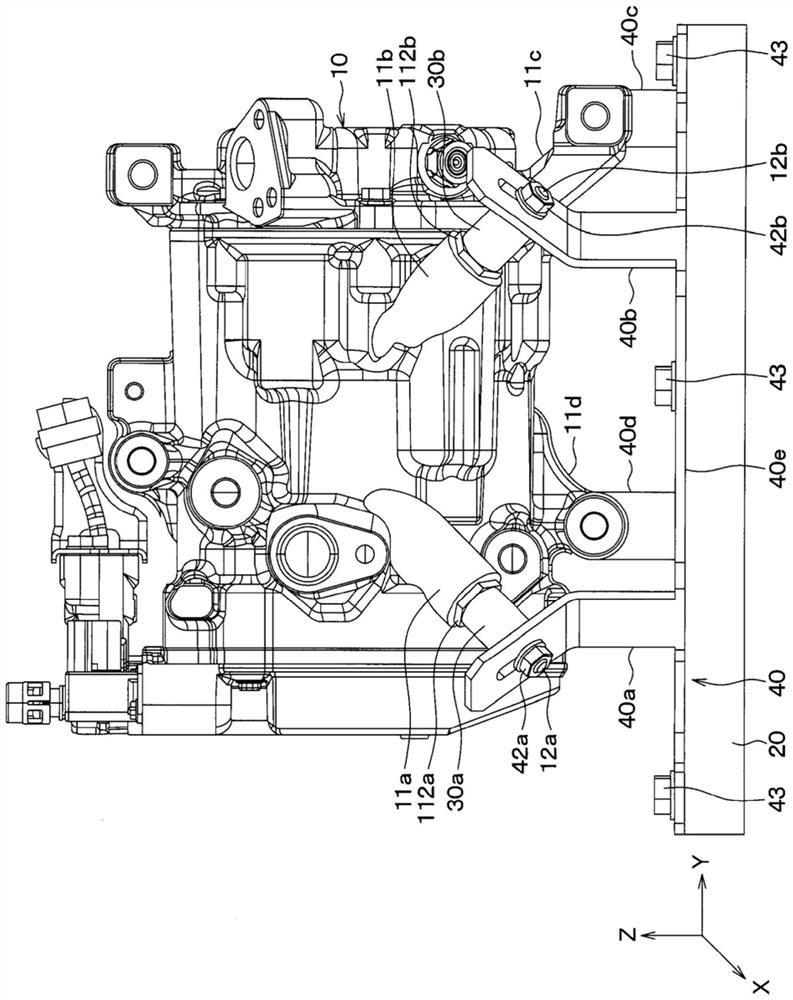
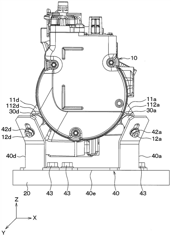
[0107] figure 1 , figure 2 , Figure 3A , Figure 3B , Figure 3C , Figure 4 A first embodiment of a vibration isolator for a compressor for an in-vehicle air conditioner is shown. The anti-vibration device of the present embodiment performs anti-vibration for suppressing the transmission of vibration generated from the compressor 10 for an in-vehicle air conditioner to the vehicle body 20 .
[0108] Hereinafter, in order to simplify the description, the compressor 10 for an in-vehicle air conditioner is simply referred to as the compressor 10 . As the compressor 10 of the present embodiment, an electric compressor in which a compression mechanism is driven by a built-in electric motor is used.
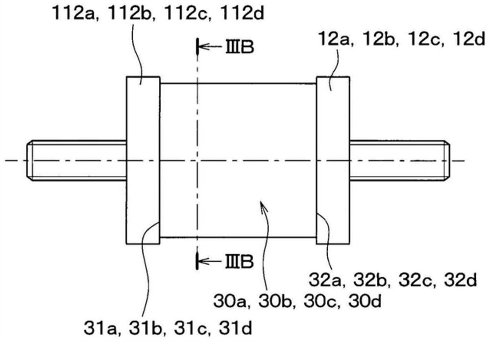
[0109] like figure 1 , figure 2 As shown, the anti-vibration device of the present embodiment includes one compressor 10 and four elastic members 30a, 30b, 30c, and 30d. Hereinafter, the four elastic members 30a, 30b, 30c, and 30d are simply referred to as elastic members ...
no. 2 approach
[0245] In the above-described first embodiment, an example in which the compressor 10 is arranged on the upper side of the vehicle body 20 has been described, and refer to Figure 22 , Figure 23 The second embodiment of the present invention in which the compressor 10 is instead arranged on the lower side of the vehicle body 20 will be described.
[0246] In the present embodiment and the above-described first embodiment, only the arrangement relationship between the vehicle body 20 and the compressor 10 is different, and the other structures are substantially the same.
[0247] In this embodiment, the arrangement relationship of the end faces 31a, 31b, 31c, 31d of the elastic members 30a, 30b, 30c, 30d, the reference points A, B, C, D, the point P, and the point Q are as follows Figure 24 , Figure 25 shown.
[0248] In the present embodiment, the elastic member 30a is supported by the leg portion 11a of the compressor 10 via the attachment member 13a. The elastic membe...
no. 3 approach
[0258] In the third embodiment, refer to Figure 26 , Figure 27 An example in which the hammer portion 14 is provided in the compressor 10 of the first embodiment described above will be described.
[0259] The compressor 10 in this embodiment is the same as the compressor 10 in the above-described first embodiment except for the hammer portion 14, and therefore, the description of the structure other than the hammer portion 14 is omitted. exist Figure 26 , Figure 27 in, with figure 1 , figure 2 The same symbols denote the same components, and their descriptions are omitted.
[0260] The weight portion 14 is arranged on the lower side in the vertical direction in the compressor 10 . The hammer portion 14 serves to lower the position G of the center of gravity of the compressor 10 as compared with the compressor 10 in the above-described first embodiment.
[0261] Here, when it is higher than the center of gravity position G of the compressor 10 (refer to Figure 2...
PUM
 Abstract
Description
Claims
Application Information
 - R&D
- Intellectual Property
- Life Sciences
- Materials
- Tech Scout
- Unparalleled Data Quality
- Higher Quality Content
- 60% Fewer Hallucinations
Browse by: Latest US Patents, China's latest patents, Technical Efficacy Thesaurus, Application Domain, Technology Topic, Popular Technical Reports.
© 2025 PatSnap. All rights reserved.Legal|Privacy policy|Modern Slavery Act Transparency Statement|Sitemap|About US| Contact US: help@patsnap.com