Steel rail milling and grinding cutter and milling and grinding blade service life simulation experiment equipment and experiment method

A rail and milling technology, which is applied in the field of rail milling and grinding tools, can solve the problems of long test period, blade scrapping, track damage, etc., and achieve good milling effect, protection of the blade and track, and milling safety.

Inactive Publication Date: 2021-09-17
SICHUAN GUANGZHENG TECH
View PDF20 Cites 1 Cited by
  • Summary
  • Abstract
  • Description
  • Claims
  • Application Information

AI Technical Summary

Problems solved by technology

The most widely used milling and shaping process is to equip the rail milling and grinding car with milling blades for shaping. Before using the milling blades, it is necessary to conduct experiments on the specific life of the blades and the performance under different parameter conditions. The existing milling blade life simulation The experimental equipment can only choose the best material

Method used


Image

  • Steel rail milling and grinding cutter and milling and grinding blade service life simulation experiment equipment and experiment method
  • Steel rail milling and grinding cutter and milling and grinding blade service life simulation experiment equipment and experiment method
  • Steel rail milling and grinding cutter and milling and grinding blade service life simulation experiment equipment and experiment method

Examples


Embodiment Construction

[0046] In order to make the purpose, technical solutions and advantages of the present invention clearer, the present invention will be further described in detail below in conjunction with the examples and accompanying drawings. As a limitation of the present invention.

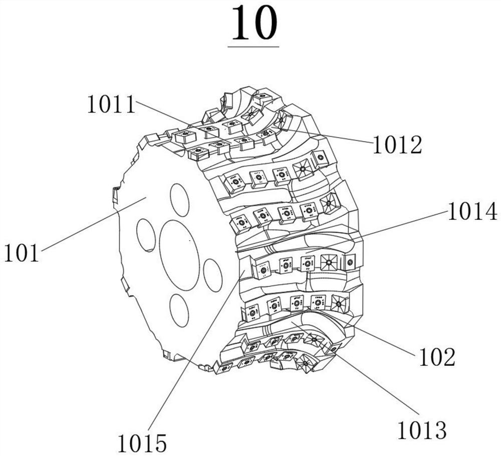
[0047] like figure 1 , figure 2 and image 3 As shown, the first embodiment of the present invention provides a rail milling tool 10, which at least includes a milling cutter disc 101 and several groups of milling cutter groups 102, and several groups of milling cutter groups 102 are arranged on the outer contour of the milling cutter disc 101 face.

[0048] When the rail milling and grinding tool 10 is in use, the milling cutter head 101 can be connected to the driving device through a connecting piece to drive its rotation. The driving device can be a common milling machine, grinding machine, drilling machine, etc., and several groups of milling cutter groups 102 are connected to The outside of the mi...


PUM


Abstract

The invention discloses a steel rail milling and grinding cutter which comprises a milling cutter disc. The milling cutter disc is provided with multiple milling cutter sets, each milling cutter set is provided with two rows of milling cutters, and each row of milling cutters comprises square milling and grinding blades and arc-shaped milling and grinding blades. The square milling and grinding blades in each row of milling cutters are arranged in the axial direction of the milling cutter disc, and the square milling and grinding blades in every two rows of milling cutters are arranged in a staggered manner, so that the projections of cutting edges of the square milling and grinding blades in every two rows of milling cutters in the radial direction of the milling cutter disc form a continuous first cutting edge line. The arc-shaped milling and grinding blades in every two rows of milling cutters are arranged in the axial direction of the milling cutter disc and are mutually staggered, so that the projections of cutting edges of the arc-shaped milling and grinding blades in every two rows of milling cutters in the radial direction of the milling cutter disc form a continuous second cutting edge line. The first cutting edge lines and the second cutting edge lines are mutually continuous to form a steel rail milling and grinding line. The square milling and grinding blades and the arc-shaped milling and grinding blades are reasonably arranged, so that the contact surface with a steel rail is smoother during milling and grinding, the milling and grinding effect is good, and the blades and the rail can be well protected.

Description

technical field [0001] The invention relates to the technical field of rail milling, in particular to a rail milling tool. Background technique [0002] The rail materials widely used in my country's railways are U71Mn and U75V. These two rail materials are typical high-manganese alloy steels with good microstructure toughness, plasticity and fatigue properties. They are relatively stable steels among high-strength rails in China. kind. During the long-term service of the rail, due to the periodic rolling, friction, and impact of the wheels, a series of diseases will appear on the rail. Defects such as cracks (local micro-fatigue cracks on the surface), rail side wear, crushing, and corrosion. [0003] Rail diseases mainly use rail milling and grinding machines to carry out on-site milling and shaping of the rails to overcome the diseases. The most widely used milling and shaping process is to equip the rail milling and grinding car with milling blades for shaping. Before ...

Claims


Application Information

Patent Timeline
IPC IPC(8): B23C5/00B23C5/02G01M13/00
CPCB23C5/00B23C5/02G01M13/00
Inventor 周磊陈辉邓林胡登文谢韶陈林
Owner SICHUAN GUANGZHENG TECH
Why Eureka
Try Eureka