Pulley support machining clamp and machining method

The technology of a pulley bracket and processing method is applied in the direction of manufacturing tools, metal processing equipment, metal processing machine parts, etc., which can solve problems such as difficult clamping and measurement, long processing cycle, and overall complexity, so as to reduce the number of clamping switching, The effect of improving processing efficiency and improving firmness

Active Publication Date: 2021-09-17
CHINA HANGFA GUIZHOU LIYANG AVIATION POWER CO LTD
View PDF7 Cites 1 Cited by
  • Summary
  • Abstract
  • Description
  • Claims
  • Application Information

AI Technical Summary

Problems solved by technology

[0004] During actual processing, because the blank is a special-shaped cavity structure, and the shapes of the left and right lower ends are arc-shaped (corresponding to the arc-shaped surface 51 at the left end of the bracket and the arc-shaped surface 52 at the right end of the bracket), there is a bearing installation end surface 54 at the upper end. There are multiple mounting side holes 56 on the surface of both ends that need to be processed, and the relevant dimensions are mostly space dimensions. The whole is more complicated, the wall is thinner, and it is not easy to clamp and measure, resulting in a longer processing cycle and higher cost for this type of product. Difficult to pass

Method used


Image

  • Pulley support machining clamp and machining method
  • Pulley support machining clamp and machining method
  • Pulley support machining clamp and machining method

Examples


Embodiment Construction

[0041] The present invention will be further described below in conjunction with accompanying drawing and specific embodiment, but should not be interpreted as that the scope of the subject matter of the present invention is only limited to following embodiment, under the situation of not departing from above-mentioned technical thought of the present invention, all according to this field Various modifications, substitutions and alterations made by ordinary technical knowledge and common means are included in the scope of the present invention.

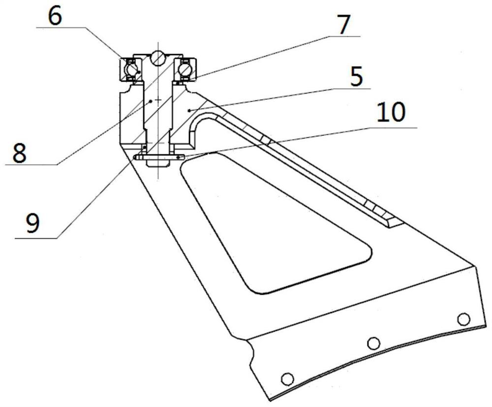
[0042] see figure 1 , The pulley bracket 5 is equipped with a ball bearing 6, a washer 7, a pin subassembly 8, a flower nut 9 and a cotter pin 10. The blanks of the pulley bracket 5 are all castings made of ZTC4, and the casting is a special-shaped cavity, wherein there is a protrusion 57 in the special-shaped cavity, and there is a clip greater than 90° between the two inner surfaces connected by the protrusion 57. horn. like Fi...


PUM


Abstract

The invention discloses a pulley support machining clamp and machining method. The machining clamp comprises a base, a pressing plate, a screw and a nut, a continuous supporting face is arranged on the surface of the base, and the supporting face extends from a mounting side hole in the left end of a pulley support to a mounting side hole in the right end of the pulley support. During machining, two datum planes are linearly cut on a pulley support casting blank, then the pulley support is clamped through the clamp, a support left end arc-shaped face and a support right end arc-shaped face are milled on a five-axis numerical control milling machine, then a bearing mounting end face is milled, a pin shaft hole is drilled and bored, and finally the mounting side hole is drilled. The machining clamp is simple in structure and firm in clamping, the pulley support is not prone to deformation and easy to measure, by means of the machining method, machining of all machining elements can be completed through one-time clamping, the machining efficiency is high, and the quality is guaranteed.

Description

technical field [0001] The invention belongs to the field of aero-engine manufacturing, in particular to a processing jig for a pulley bracket product and a processing method for a pulley bracket using the jig. The processing jig and processing method can be extended to pulley bracket products with similar structures. Background technique [0002] The pulley bracket 5 is an important part installed on the engine, see figure 1 , The pulley bracket 5 is equipped with a ball bearing 6, a washer 7, a pin subassembly 8, a flower nut 9 and a cotter pin 10. The blanks of the pulley bracket 5 are made of ZTC4 castings, which have good casting performance and corrosion resistance. [0003] like Figure 7 , the pulley bracket 5 finally needs to be assembled with a ball bearing 6, and the verticality requirement of the pin shaft hole 55 on the bearing installation end surface 54 for the bearing installation end surface 54 is And the precision of the pin hole 55 is higher, not more ...

Claims


Application Information

Patent Timeline
Patent Type & Authority Applications(China)
IPC IPC(8): B23P15/00B23Q3/06
CPCB23P15/00B23Q3/06
Inventor 简洪健王维林肖敏男孙登霞严笑梅丁代华吴东华邓开富
Owner CHINA HANGFA GUIZHOU LIYANG AVIATION POWER CO LTD
Why Eureka
Try Eureka