
Unmanned aerial vehicle airborne photoelectric pod lifting system

A technology of photoelectric pod and lifting system, applied in the field of unmanned aerial vehicle, can solve the problems of more consumption and inability to put the photoelectric pod into the cabin of the unmanned aerial vehicle in time, so as to prolong the battery life, balance the gravity and energy. reduced effect

Active Publication Date: 2021-09-17
FUZHOU COLLEGE OF FOREIGN STUDIES & TRADE
View PDF5 Cites 0 Cited by
  • Summary
  • Abstract
  • Description
  • Claims
  • Application Information

AI Technical Summary

Problems solved by technology

[0003] However, during the shooting period, in order to shoot the target from multiple angles and a wider angle of view, the UAV is often required to take long-term continuous shooting in the flying state, and the photoelectric pod is always outside the UAV during this process, so that the wireless Man-machines need to consume more energy to balance the resistance encountered when the photoelectric pod moves. In addition, the existing UAV lifting system can only extend or retract the photoelectric pod into the UAV cabin at a constant speed. When there is no When the man-machine encounters an emergency and needs to fly away from the shooting scene quickly, and at the same time put the photoelectric pod into the UAV cabin, the existing UAV lifting system cannot timely put the photoelectric pod into the UAV cabin

Method used


Image

  • Unmanned aerial vehicle airborne photoelectric pod lifting system
  • Unmanned aerial vehicle airborne photoelectric pod lifting system
  • Unmanned aerial vehicle airborne photoelectric pod lifting system

Examples


Embodiment Construction

[0029] In order to make the purpose, technical solutions and advantages of the embodiments of the present invention more clear, the technical solutions in the embodiments of the present invention will be clearly and completely described below in conjunction with the accompanying drawings in the embodiments of the present invention. Obviously, the described embodiments It is a part of embodiments of the present invention, but not all embodiments. Based on the embodiments of the present invention, all other embodiments obtained by persons of ordinary skill in the art without making creative efforts belong to the protection scope of the present invention.

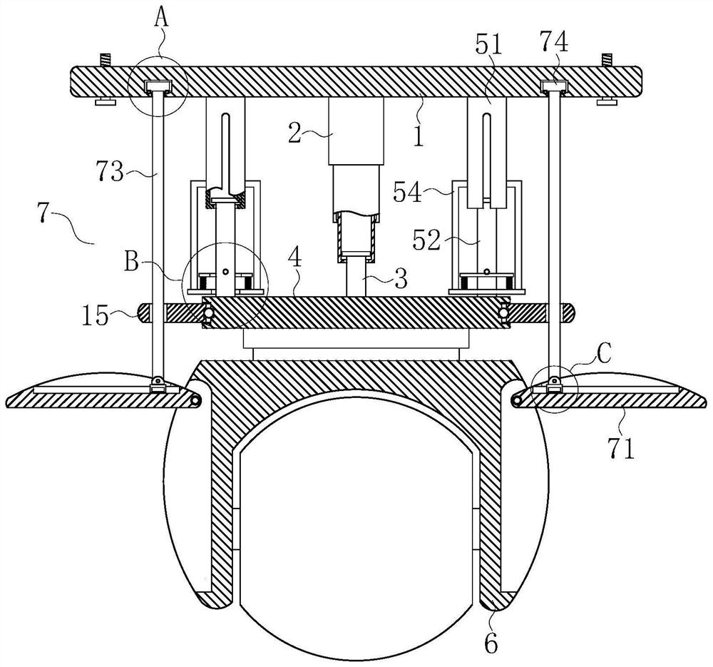
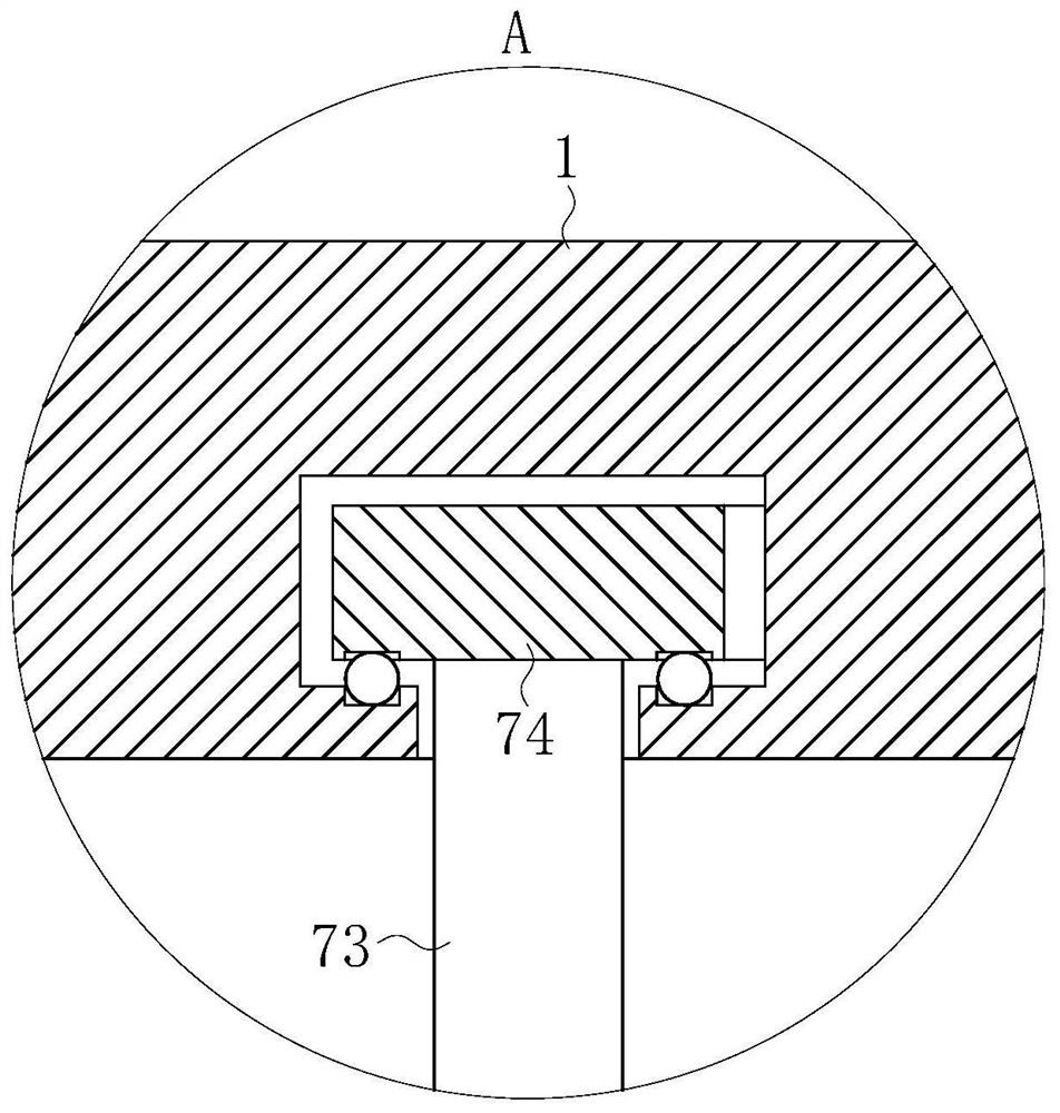
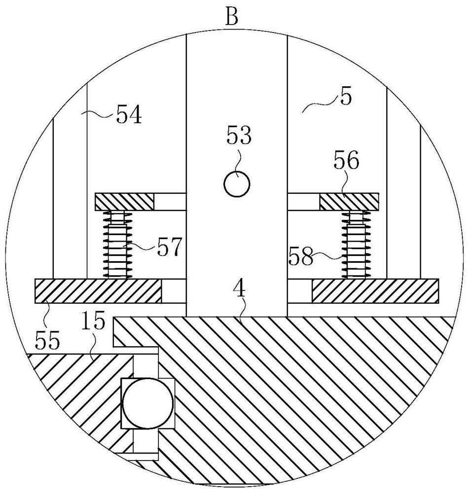
[0030] The present invention provides such Figure 1-6 The shown a kind of UAV airborne photoelectric pod lifting system includes a fixed plate 1, the bottom of the fixed plate 1 is fixedly connected with an electric telescopic rod 2, and the bottom of the electric telescopic rod 2 is slidably connected with a movable rod 3. ...


PUM


Abstract

The invention belongs to the technical field of unmanned aerial vehicles, and particularly relates to an unmanned aerial vehicle airborne photoelectric pod lifting system which comprises a fixed plate, an electric telescopic rod is fixedly connected to the bottom of the fixed plate, a movable rod is slidably inserted into the bottom of the electric telescopic rod, and a mounting plate is fixedly connected to the bottom of the movable rod. Two springback devices are arranged between the mounting plate and the fixing plate, the bottom of the mounting plate is rotationally connected with a photoelectric pod, storage grooves are formed in the two sides of the photoelectric pod, and lifting devices are arranged in the storage grooves. By arrangement of the springback devices, when the unmanned aerial vehicle encounters an emergency situation and needs to rapidly fly away from a photographing site, the unmanned aerial vehicle suddenly accelerates, the lifting device generates upward supporting force on the photoelectric pod at the moment, so that the pulling force borne by the electric telescopic rod is reduced, and meanwhile, the springback devices synchronously pulls the photoelectric pod upwards. Therefore, the photoelectric pod can be quickly retracted in cooperation with the electric telescopic rod.

Description

technical field [0001] The invention belongs to the technical field of unmanned aerial vehicles, in particular to an onboard photoelectric pod lifting system of an unmanned aerial vehicle. Background technique [0002] UAV photoelectric pod is a kind of UAV pod, generally composed of visible light camera, infrared core, signal processing unit, image compression unit, stable platform unit, etc., has the function of taking pictures and video, and can realize all-weather Tracking, photography, and monitoring of long-distance targets; when the UAV is in a non-photographing state, the photoelectric pod is generally stored in the cabin at the bottom of the UAV, which can reduce the resistance of the UAV during flight. In addition, when the UAV lands, it can also avoid the collision between the photoelectric pod and the ground. When shooting is required, the photoelectric pod extends out of the cabin under the action of the UAV's lifting system, so as to meet the multi-angle requir...

Claims


Application Information

Patent Timeline
IPC IPC(8): B64D47/08B64C39/02
CPCB64D47/08B64C39/02B64U2101/30
Inventor 周硕聪陈章斌曾姣艳周硕雄
Owner FUZHOU COLLEGE OF FOREIGN STUDIES & TRADE
Learn More