Jacking equipment of steel structure beam for installation of small factory building

A technology for installation of steel structure beams, applied in the direction of lifting frame, lifting device, building structure, etc., can solve the problems of steel structure beam sliding, steel structure beam position adjustment, difficult to reach, etc.

Active Publication Date: 2021-09-17
烟台华虹建筑科技有限公司
View PDF8 Cites 0 Cited by
  • Summary
  • Abstract
  • Description
  • Claims
  • Application Information

AI Technical Summary

Problems solved by technology

[0004] When the above-mentioned equipment is in use, there are many deficiencies. First, when the steel structure beam is lifted, the two jacking mechanisms carry the load on the steel structure beam, but during the lifting process, the steel structure beam is not placed in the horizontal position and the vertical position. If the position is fixed, the steel structure beam will slide and fall; second, in the actual installation process, the position of the steel structure beam is between the two beams, but the length of the steel structure beam is actually greater than or equal to the length of the two beams distance, the above-mentioned equipment lifts the steel structure beam in a horizontal state, and it is difficult for the steel structure beam to

Method used


Image

  • Jacking equipment of steel structure beam for installation of small factory building
  • Jacking equipment of steel structure beam for installation of small factory building
  • Jacking equipment of steel structure beam for installation of small factory building

Examples


Embodiment Construction

[0035] In order to make the objectives, technical solutions and advantages of the present invention clearer, the technical solutions of the present invention will be clearly and completely described below with reference to the specific embodiments of the present invention and the corresponding drawings. Obviously, the described embodiments are only some, but not all, embodiments of the present invention. Based on the embodiments of the present invention, all other embodiments obtained by those of ordinary skill in the art without creative efforts shall fall within the protection scope of the present invention.

[0036] The technical solutions provided by the embodiments of the present invention will be described in detail below with reference to the accompanying drawings.

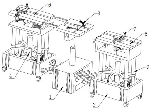
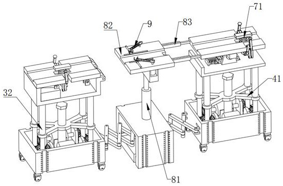
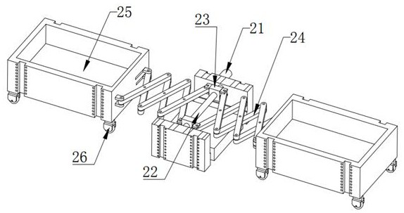
[0037] refer to Figure 1 to Figure 12 As shown, the embodiment of the present invention provides a lifting device for a steel structure beam for small workshop installation, including a work box 1, a movi...


PUM


Abstract

The invention discloses jacking equipment of a steel structure beam for installation of a small factory building, and belongs to the technical field of construction appliances. The jacking equipment comprises a working box, and further comprises a moving mechanism, an elevating mechanism, an auxiliary mechanism, a limiting mechanism, a beam pushing mechanism and two lifting mechanisms, the moving mechanism is installed on the working box, the two lifting mechanisms are installed at the two ends of the moving mechanism correspondingly, the elevating mechanism is installed on one lifting mechanism, the auxiliary mechanism is installed on the other lifting mechanism, the limiting mechanism is installed on the auxiliary mechanism and the elevating mechanism, and the beam pushing mechanism is installed above the working box. According to the jacking equipment of the steel structure beam for installation of the small factory building, the limiting mechanism limits the vertical position of the steel structure beam, then the elevating mechanism and the auxiliary mechanism are matched to obliquely lift the steel structure beam to the position above a factory building cross beam, and then the beam pushing mechanism is used for adjusting the horizontal position of the steel structure beam to make the steel structure beam aligned with a mounting station.

Description

technical field [0001] The invention relates to the technical field of construction tools, in particular to a lifting device for a steel structure beam for installation of a small workshop. Background technique [0002] Steel structure is a structure mainly made of steel and is one of the main types of building structures. The characteristics of steel are high strength, light weight and high rigidity, so it is especially suitable for the construction of large-span and super-high and super-heavy buildings; the material has good homogeneity and isotropy, and is an ideal elastic body, which is most suitable for general engineering. The basic assumptions of mechanics; the material has good plasticity and toughness, can have large deformation, and can withstand dynamic loads well; construction period is short; , Good airtightness, so it can be used to build gas tanks, oil tanks and transformers, etc. It is mainly used for load-bearing skeletons of heavy workshops, workshop struc...

Claims


Application Information

Patent Timeline
IPC IPC(8): B66F7/10B66F7/14B66F7/22B66F7/28E04G21/16
CPCB66F7/10B66F7/14B66F7/22B66F7/28E04G21/163
Inventor 陈丽军孙磊陈明山
Owner 烟台华虹建筑科技有限公司
Why Eureka
Try Eureka