
Network connector mounting base

A technology of network connectors and mounting seats, which is applied to network connectors, components of connection devices, connections, etc., can solve problems such as low assembly efficiency, reduced service life, and impact on data transmission quality, so as to improve assembly efficiency and improve use Longevity, the effect of ensuring smooth communication

Active Publication Date: 2021-09-17
浙江劳兰信息技术有限公司 +1
View PDF5 Cites 0 Cited by
  • Summary
  • Abstract
  • Description
  • Claims
  • Application Information

AI Technical Summary

Problems solved by technology

[0002] The existing network cable connector mounting seat on the market has a simple structure. After being assembled with the network cable connector panel and the distribution frame, the network cable connector mounting seat cannot be rotated, so that after the network cable connector is inserted, whether it is an incoming or outgoing network cable None of them can be rotated, and in actual wiring, the network cable generally needs to be routed close to the wall. Since the network cable cannot be rotated, it can only bend the network cable. Over time, it is easy to bend or even break the network cable at the joint, which will affect the data. The transmission quality reduces the service life, and the wiring is not beautiful; at the same time, when the existing network cable connector mounting seat is assembled with the network cable connector panel and the distribution frame, it must be inserted with great force, and the disassembly requires a screwdriver to pry it out, and the assembly efficiency Low, easy to damage, easy to injure the operator

Method used


Image

  • Network connector mounting base
  • Network connector mounting base
  • Network connector mounting base

Examples


Embodiment Construction

[0026] In describing the present invention, it should be understood that the terms "center", "longitudinal", "transverse", "upper", "lower", "front", "rear", "left", "right", " The orientations or positional relationships indicated by "vertical", "horizontal", "top", "bottom", "inner" and "outer" are based on the orientations or positional relationships shown in the drawings, and are only for the convenience of describing the present invention and Simplified descriptions, rather than indicating or implying that the device or element referred to must have a particular orientation, be constructed and operate in a particular orientation, and thus should not be construed as limiting the invention. In addition, the terms "first", "second", etc. are used for descriptive purposes only, and should not be interpreted as indicating or implying relative importance or implicitly specifying the quantity of the indicated technical features. Thus, a feature defined as "first", "second", etc....


PUM


Abstract

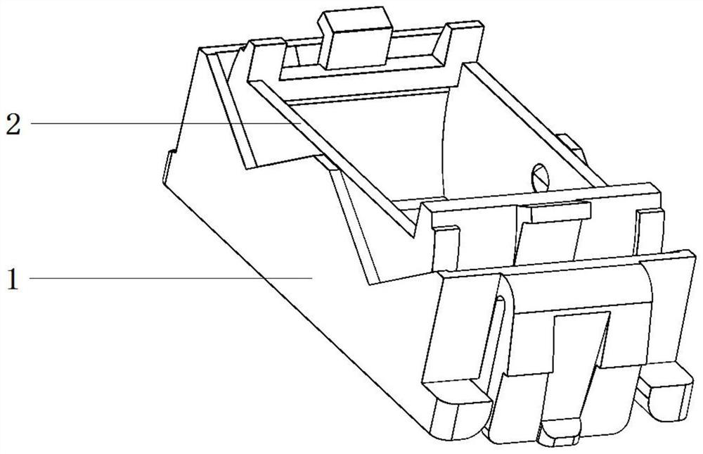
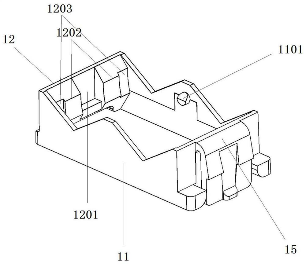
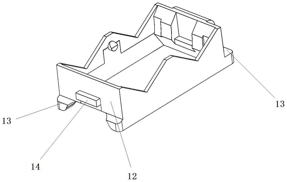
The invention discloses a network connector mounting base which comprises a mounting base body; a swing part is connected to the inner wall of the mounting base body in a clamped mode; the mounting base body comprises two first side plates and two first clamping plates which are symmetrically arranged; a buckle is integrally fixed to the middle of the upper portion of each first side plate; first clamping grooves are symmetrically formed in the opposite sides of the two first clamping plates; first clamping blocks are arranged on the two sides of each first clamping groove correspondingly; second clamping grooves are formed in the two sides of each first clamping block correspondingly; the swing part is clamped to the inner wall of the mounting base body; the mounting base body is provided with the buckles, the first clamping grooves, the first clamping blocks and the second clamping grooves; the swing part is provided with a clamping hole, a third clamping block and a fourth clamping block; slopes are arranged on the upper surface and the lower surface of the first clamping block; and concave surfaces are arranged in the middle of the first clamping block and the middle of the second clamping groove, the outer surface of each second clamping plate is arc-shaped, and the swing part can swing left and right in the mounting base body.

Description

technical field [0001] The invention relates to the field of network equipment, in particular to a network connector installation seat. Background technique [0002] The existing network cable connector mounting seat on the market has a simple structure. After being assembled with the network cable connector panel and the distribution frame, the network cable connector mounting seat cannot be rotated, so that after the network cable connector is inserted, whether it is an incoming or outgoing network cable None of them can be rotated, and in actual wiring, the network cable generally needs to be routed close to the wall. Since the network cable cannot be rotated, it can only bend the network cable. Over time, it is easy to bend or even break the network cable at the joint, which will affect the data. The transmission quality reduces the service life, and the wiring is not beautiful; at the same time, when the existing network cable connector mounting seat is assembled with t...

Claims


Application Information

Patent Timeline
Patent Type & Authority Applications(China)
IPC IPC(8): H01R13/502H01R13/56H01R35/00
CPCH01R13/502H01R13/562H01R35/00H01R2201/04
Inventor 汪来兵邓涛
Owner 浙江劳兰信息技术有限公司
Learn More