Tool magazine of machine tool

A tool magazine and machine tool technology, which is applied to metal processing machinery parts, clamping, support, etc., can solve the problems of reduced space utilization, increased manufacturing costs, and equipment weight, so as to save maintenance costs, reduce replacement time, and save The effect of overhead

Active Publication Date: 2021-09-17
DN SOLUTIONS CO LTD
View PDF5 Cites 2 Cited by
  • Summary
  • Abstract
  • Description
  • Claims
  • Application Information

AI Technical Summary

Problems solved by technology

That is, when the stroke in the width direction is larger than 2m, there is a risk of interference and collision with the workpiece because the spindle needs to reciprocate in a long section between the tool magazine fixed on the side of the equipment and the ATC for tool replacement. bigger problem
[0017] In particular, since the clamping part of the existing tool magazine uses a ball with spring tension to clamp the pull stud, the ATC must be raised when the clamping part of the tool magazine and the spindle retract the tool toward the ATC or draw the tool from the ATC. and down, and other components for lifting are required, so there is a problem that the structure of the ATC becomes complicated, and the ATC becomes larger, which eventually leads to a larger machine tool
[0018] In addition, in order to reduce the risk of interference and collision in the existing machine tools, the utilization rate of the space decreases with the increase of the equipment, the inconvenience is brought about by the increase of the equipment, and the manufacturing cost and maintenance cost of the equipment increase.
[0019] In addition, in existing machine tools, the ATC needs to move up and down to replace the tool while rotating on the spindle, so there are problems in that the size of the ATC itself increases, the weight of the equipment increases, and the manufacturing cost increases.

Method used


Image

  • Tool magazine of machine tool
  • Tool magazine of machine tool
  • Tool magazine of machine tool

Examples


Embodiment Construction

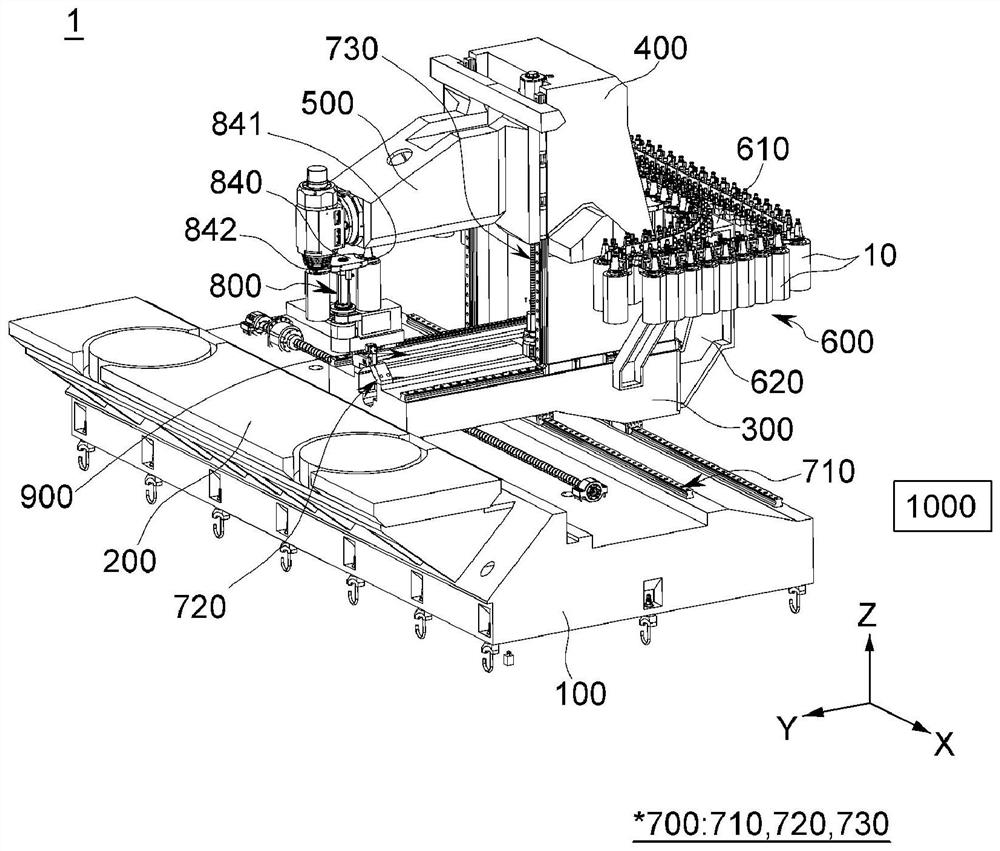
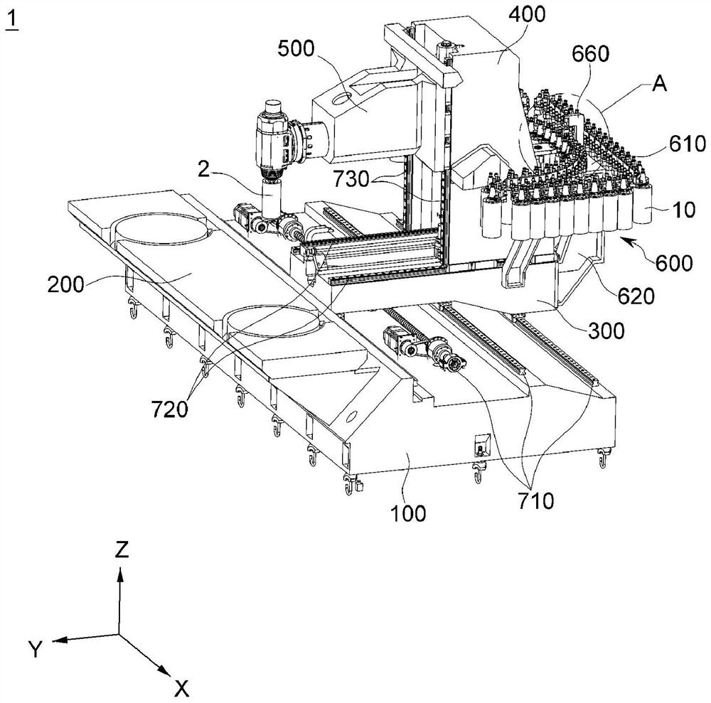
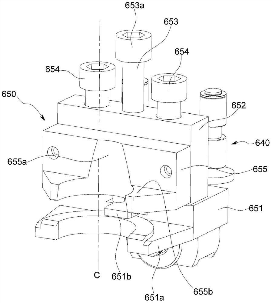
[0058] The tool magazine of a machine tool according to an embodiment of the present invention will be described in detail below with reference to the accompanying drawings. The embodiments introduced below are provided as examples in order to fully convey the idea of ​​the present invention to those skilled in the art. Therefore, the present invention is not limited to the embodiments described below, and may be embodied in other forms. In addition, in the drawings, the size, thickness, etc. of the device may be enlarged for convenience. The same reference numerals denote the same constituent elements throughout the specification.

[0059] The advantages, features of the present invention and methods of achieving them may be discussed with the appendix Figure 1 This will become apparent with reference to the embodiments described in detail later. However, the present invention is not limited to the embodiments disclosed below, but is constituted by various forms different...


PUM


Abstract

The present invention relates to a tool magazine of a machine tool, such as a column moving type machining center, wherein when a tool is replaced by a tool replacing part and a tool replacing part transfer part, a tool accommodated in a clamping part of a tool magazine unit is introduced or extracted from a direction perpendicular to the axis of the tool, and a flange part of the tool is directly clamped by a holding part of a replacing arm, thereby replacing the tool with the tool replacing part and the tool replacing part transfer part. In the medium-sized or large-sized machine tool having a long length in the width direction, the tool changing time can be shortened, the productivity can be improved, and the stability and reliability can be improved by minimizing collision or mechanical interference, wherein the tool magazine unit is provided on a saddle, a tool changing part is movably provided on the saddle, and the tool changing part is provided on the saddle. The tool changing and transferring part transfers the tool changing part independently from the stand column.

Description

technical field [0001] The present invention relates to a tool magazine for a machine tool, and more particularly, to a tool magazine for a machine tool such as a column movable machining center. The tool accommodated in the clamping portion of the tool magazine unit can be introduced or drawn in a direction at right angles to the axis of the tool, thereby shortening the tool changing time and improving productivity, wherein the tool magazine unit is provided on the saddle, and the tool changing portion can It is installed on the saddle so as to be movable, and the tool change transfer part and the column independently transfer the tool change part. Background technique [0002] In general, a machine tool refers to a machine used for the purpose of machining a metal / non-metal workpiece into a desired shape and size with an appropriate tool by various cutting or non-cutting methods. [0003] Various machine tools such as turning centers, vertical / horizontal machining centers...

Claims


Application Information

Patent Timeline
Patent Type & Authority Applications(China)
IPC IPC(8): B23Q3/155B23Q3/16
CPCB23Q1/626B23Q3/15724B23Q3/15766B23Q3/15713B23Q2003/155418B23Q2003/155428B23Q2003/155446B23Q3/16B23Q3/15513B23Q3/15526
Inventor 郑圣勋
Owner DN SOLUTIONS CO LTD
Why Eureka
Try Eureka