Method and device for producing agglomerated stone with controllable patterns

A production device and stone technology, which are applied in the field of stone production methods and devices with controllable patterns, can solve problems such as low production quality and efficiency, inability to produce patterns, and inability to produce regular patterns, so as to improve production efficiency and improve productivity. Quality, time saving effect

Pending Publication Date: 2021-09-21
崔向东
0 Cites 0 Cited by

AI-Extracted Technical Summary

Problems solved by technology

[0019] So to sum up, at present, the granite square materials can only produce random and disordered short patterns, or do surface coating later, but it is still impossible to produce...

Method used

Different from the random drop of the stone material in the prior art, now the stone material falls into the funnel 410, and it will flow out from the lower mouth under its own weight, and the decorative pattern is forced to be stretched and tiled in one direction, and the pattern coming out It is a long parallel grain. If the material in the funnel falls unevenly, the place with a lot of material will be pressed down and become "mountain pattern". Controlling the density of the patterns can result in parallel and neat dense patterns or sparse long patterns. That is to say, by stirring the main and auxiliary materials of different colors (or spraying or powdering) in the mixer, and flowing down from the "funnel" during the blanking process, the pattern direction is consistent, thus forming a long and coherent pattern. pattern. In this way, by controlling the proportion of main material and auxiliary material, spraying, and powdering, the number of patterns can be controlled; by controlling the length of time for the main mixer to stir the patterns, the thickness and distribution density of the patterns can be controlled; and by controlling the moving speed of the trolley Cooperating with the blanking speed, it can control the material not to break, so as to achieve the continuity of the pattern, and also control the density of the pattern to a certain extent.
[0179] According to the second type of embodiment of the present invention, the granite production device and method with controllable patterns change the way of material dropping from dropping to flowing out through the funnel, which overcomes the tra...

Abstract

The invention discloses a method and a device for producing a agglomerated stone with controllable patterns. The device comprises a stirrer; a blanking chamber; a movable mold; a pressing chamber; a cutting device; a polishing and waxing device; and any one or more of a plate, with a preset horizontal section shape, an enclosure frame and a patterned material molded and formed in advanced, wherein the plate, the enclosure frame and the patterned material can be vertically placed on in the movable mold, the surface of the plate is coated with a pigment, the enclosure frame is enclosed by plates and is filled with the pigment, a lifting device is arranged at the upper end of the plate and/or the enclosure frame and used for moving the plate and/or the enclosure frame out of the movable mold after discharging is finished, the pigment is reserved in the agglomerated stone material, so that preset patterns are formed in the agglomerated stone material; the pattern material comprises one or more sections, and each section of the pattern materials has a similar preset horizontal section shape and is staggered from one another.

Application Domain

Technology Topic

PhysicsColourant +2

Image

  • Method and device for producing agglomerated stone with controllable patterns
  • Method and device for producing agglomerated stone with controllable patterns
  • Method and device for producing agglomerated stone with controllable patterns

Examples

  • Experimental program(1)

Example Embodiment

[0104] Embodiments of the present invention will be described in detail below with reference to the accompanying drawings. In the following description, many specific details are set forth in order to make those skilled in the art will more fully understand the present invention. However, those skilled in the art will apparently, the implementation of the present invention may not have some of these specific details. Furthermore, it should be understood that the invention is not limited to the particular embodiments described. Instead, the present invention can be implemented in accordance with any combination of features and elements below, regardless of whether they involve different embodiments. Thus, the following aspects, features, embodiments, and advantages are used only by way of illustration without being considered as a claimed, unless explicitly proposed in the claims.
[0105] The meaning of the various terms involved in this specification is generally generally meanings in the art, or meanings normally understood by those skilled in the art after reading this specification. The term "comprising" in this specification, "comprising" is open, that is, in addition to the various elements mentioned, it may also include other unexpected elements. For example, the apparatus and method of the present invention described in this specification may include other conventional components or steps known to those skilled in the art, such as the background techniques of this specification, in addition to the components or steps specified in the present specification. Parts or steps mentioned in part. Similar terms "Connect", "connected", "connected", such as the term, "connected",,,,,,,,,,,,,,,,,,,,,,,,,,,,,,,,,,,,,,,,,,,,,,,,,,,,,,,,,,,,,,,,,,,,,,,,,,,,,,,,,,,,,,,,,,,,,,,,,,,,,,,,,,,,,,,,,,,,,,,,. The representation of the representation of the orientation, such as "long", "wide", "high", "front", "left", "right", "upper", "under", etc. The corresponding orientation shown in the figure is represented in the figure. The dimensions of the components mentioned in this specification, each substance ingredients, and content such as the components are merely examples, not the limitation of the invention.
[0106] First type embodiment
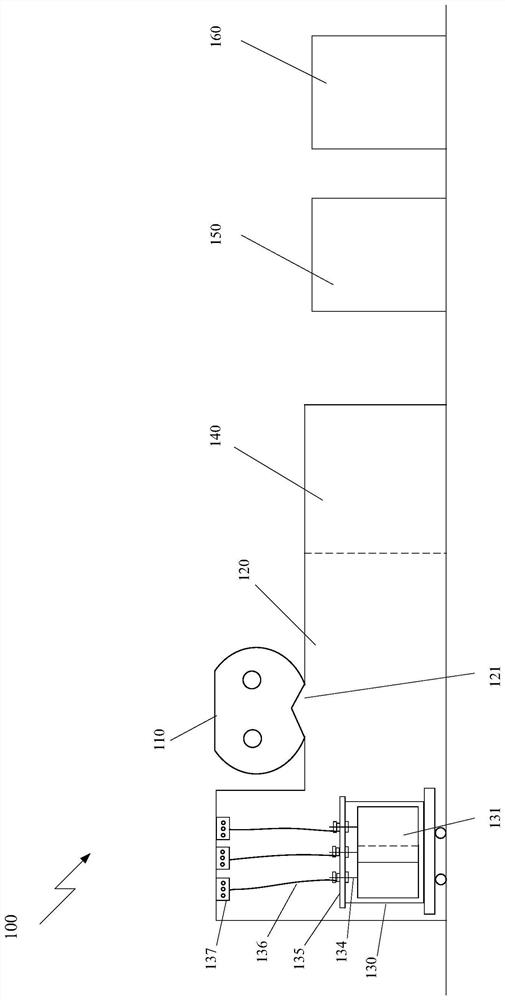
[0107] Now referring to figure 1 It shows a schematic diagram of a granite production apparatus according to a first type of embodiment of the invention.
[0108] like figure 1 As shown in the present invention, the granite production apparatus 100 according to the first type of embodiment of the invention includes:
[0109] The mixer 110 is used to stir the stone raw material as a granite;
[0110] The falling chamber 120 is located below the agitator 110, and is provided with a blasting port 121 between the mixer 110;
[0111] Movable mold 130, which is capable of entering the blanking chamber 120, so that a good stirring stone post 121 can be movable mold 130 falls off along the discharge port;
[0112] Pressing chamber 140, the chamber 120 on one side blanking and blanking chamber 120 is connected, comprising means for post stone can be pressed mold 130 is moved in the pressing means (not shown) side material, wherein said blanking pressing chamber 140 and chamber 120 can be closed and evacuated together, such that blanking and pressing operations performed in a vacuum;
[0113] Cutting means 150, a plurality of square cut into sheets by the movable mold 130 is removed;
[0114] The polishing apparatus 160 and waxing, polishing and the plate for waxing;
[0115] Can be placed vertically in the movable mold 130 and having a predetermined horizontal cross-sectional shape of the plate 131, surround, and any one or more of the pre-molded tread compound, wherein, in the plate 131 surface is coated with toner, the surround of a plate and has encircled injection toner therebetween, said upper end plate 131 and / or provided with a lifting frame enclosure means, when used after the end of the blanking plate 131 and / or surround the movable mold 130 is removed, toner will remain in the post stone, thereby forming a predetermined pattern in the post stone, the pattern material comprises one or more segments, each segment having a similar material pattern sectional shape preset level and offset from each other.
[0116] In some embodiments, the lifting device comprising:
[0117] A plurality of vertical rods fixed to the plate 131 and / or 134 of the enclosure frame;
[0118] Holder 135 may be mounted on the upper movable mold 130, the bracket 135 on positions corresponding to the plurality of rods 134 provided with a plurality of apertures, each of said plurality of rods 134 penetrates the plurality of holes;
[0119] A plurality of ropes 136, one end of each rope 136 is secured at one end 134 of the lever;
[0120] Blanking fixed within the chamber 120 at the top of the lift motor 137, with the other end of the plurality of cords 136 are connected, through said plurality of lift cords 136 of the plurality of rod 134, whereby the plate 131 and / or surround the movable mold 130 is removed.
[0121] The plate 131 may be, for example, iron plate having a thickness of 3 mm for example. Number and a preset level of the cross-sectional shape of plate 131 may be determined according to the species granite pattern desired.
[0122] The plurality of rod 134 may be, for example, a screw, one end of which is welded on one or more of the plates 131, through the other end of the stent. The stent 135 may be, for example, the support structure in an upper movable mold 130 is built for communicating with the plurality of rods secured together with the one or more plates 134 131, from its role in suspension, rather than let the vertical fall. The plurality of rope 136 may be, for example, rope.
[0123] For example, in practice, may first unsaturated resin 100 parts, was added 3 parts of hydrogenated castor oil, heated until completely dissolved, then adding an equal amount of sand and calcium carbonate powder, titanium dioxide was added to the desired oxide, yellow iron oxide, black iron oxide, red iron oxide, phthalocyanine green and the like in varying proportions of one or more colors, a paste made stand.
[0124] Then, good paste cardboard or release agent in the mold, the predetermined shape of the 3 mm thick pieces of iron vertically movable into said mold. Iron may contact the lower end of the mold bottom, the top of the die may be lower than the upper end of 30 cm, the upper end of each iron plate may be spaced 70 cm welding a diameter of 3 cm and a length of 50 cm screw (screw 10 cm iron plate embedded in the solder, 40 cm above the iron plate), the screw at this time there are still 10 cm above die. By 10 cm in the mold channel, set up "well" -shaped support 50 cm from the four sides of the mold (specifically, to follow the position of the screw, increasing the number of channel), channel puncturing positions corresponding to the screw, the screw penetration hole, then tighten the nut so that the suspension of iron play a role, so iron vertical to fail.
[0125] For example, at the uppermost end of each of the screw threaded nut, the nut is a collar connected to the lower rope, thicker than the inner diameter of the collar screw, thinner than the outer diameter of the nut. Each rope 18 mm in diameter, 8 m long, the collar welded at one end, the other end is connected to the motor lift. Lift motor mounted on top blanking chamber connected by a screw on the rope and iron. The lifting motor can be six, for example, power 3Kw, blanking the blanking opening area left chamber may be raised to 5 m, in order to enhance installation of the motor at its top.
[0126] For example, prior to lifting the iron into the mold, the first pattern of coarse iron needs to place colored paste prepared above, is required sipes paste sprayed on the iron plate (with titanium dioxide, iron oxide plus pigment paste is ground to a resin), scattered toner (toner mixed with titanium dioxide, iron oxide pigments, etc. made uniform).
[0127] Then, then lifting iron into the mold, rope connected. Then a small vehicle enters the blanking die chamber, until the main mixer stir good material, in a vacuum, the reciprocating die around the small vehicle, a main mixer blanking opening door, there is fed off a plurality of preset shape with an iron plate mold. After the completion of blanking, to below the mold-moving small vehicle lift motor blanking chamber, the lift motor so that the wire rope is pulled completely out of the mold up to the iron, and the iron cream colored paste will more than ten tons stay huddled in the material under pressure and tack material. Because the shape of the iron plate is pre-designed, so that the pattern obtained in the material is also substantially predetermined pattern.
[0128] For example, the material of the mold is then pulled to press press-forming chamber, put under vacuum, a press, allowed to stand one week, the major axis turned 90 degrees and the height axis intersecting faces, perpendicular to the height axis wool board cut, polished It can be. The iron plate and the transport wagon Chula outdoor materials, and re-apply paste is paste, for the next use.
[0129] In other embodiments, it may also be used instead of a single piece of iron surround. For example, the enclosure frame, i.e., by the two mutually parallel (or parallel) to open the upper and lower iron formed, circumferentially closed enclosure frame, the shape and surround the entire width can be set as desired. Further, it is at 50 cm intervals around the frame around the top down cut finely dispersed opening (in the case of iron without destroying the strength), so that when the vacuum inside air can be drawn. Then poured into one or several different colors box around the desired color mixing, stirring good material (e.g., on-demand formulated titanium dioxide, iron oxide pigments, calcium carbonate was added sand, calcium carbonate powder, unsaturated resin, accelerators, curing agent obtained by mixing materials), can be made very wide pattern. The number and shape of the pattern according to still iron and / or pre-set surround. Surround and iron may be used alone or in combination may be used together. The same process and then iron: blanking chamber into the main mixer blanking, iron and pulled enclosing frame, nip and the like.
[0130] In some embodiments, may also be added special materials, such as fiber optic fibers (elongated transparent), arranged in a predetermined shape on the plastic hanging sling, and the lift motor not connected to the wire rope, slings suspended above the plastic inside the mold , plastic sling hove live outside and wound on the bolt outside the mold, to ensure that the suspension does not fall. After the main mixer down into a mold, the mold carriage loaded directly into nip pressing chamber, even with the top of the press and plastic rope hanging fiber material into the fiber. After curing the material to be cut, discarded plastic sling plate above the skin, there is both below the predetermined pattern, the special sheet material, such as a light-transmitting optical fiber holes formed in a special shape.
[0131] In still other embodiments, the silica gel may also be used to mold, do two (or more pieces) mold, is made of an intermediate shape of the desired pattern (in a top view), the total height of the two molds to the pressure feed side contour, consistent pattern mold upper and lower sections, but can be displaced in a vertical position (when the press nip prevented, cured pressed against the pattern material, pattern material crushing, and after then there is a risk offset), then blend with calcium carbonate sand, calcium carbonate powder, a resin made good flowability slurry (the slurry may be a single color, may be a multicolor, color and even part of the main ingredient, and this pattern can be out Ingredients effect), pouring into the silicon under vacuum mold, pouring the material to be cured after demolding, the vertical pattern in the silicon material into the mold carriage carrying the mold, the lower mold live suffer lower, upper and lower ends of the upper end of the lower section a horizontal plane, and the lower and upper feed patterns are fixed with a rope (pull end of the rope hoist rope through the top of the play pattern material downwardly cm circular hole 20, and the other end on top of a hook, the hook a motor connected to the back et fed off material pattern can be stably stand, the motor driven rotation link is rotated, the angle of the hook to hang the rope does not, then the rope is disengaged from the hook, and emerge from the opening in the pattern material). Pattern material pulled by the rope, in a small vehicle vertical mold, the other end of the rope at the top of the elevating motor chamber blanking. After completion of the primary mixer down into a mold, rope pulled out, leaving only the pattern material is buried in the mold main ingredient, small vehicle to pressing chamber the pressing mold opening.
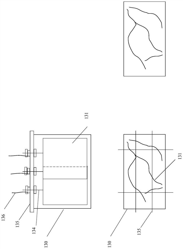
[0132] Now referring to figure 2 , Which illustrates a first class of embodiments of the present invention is a schematic front view and a horizontal sectional view of the pattern sheet produced good movable mold has been assembled, wherein the upper left picture shows a front view of a movable mold, the lower left picture shows the movable horizontal sectional view of a mold, a lower right photo shows a schematic view of the produced slabstock pattern.
[0133] like figure 2 As shown, the plurality of plates 131 are vertically mounted on a movable mold 130, the upper end plate 131 is fixed to the plurality of the plurality of lever 134. Moving the upper mold 130 may be attached to the bracket 135, the bracket 135 is composed of well-shaped channel, is provided with a plurality of holes corresponding to the plurality of rod 134 to the position of the holder 135, each rod is inserted into a hole and tighten the nuts, thereby the lever 134 and the plate 130 is fixed up. A plurality of horizontal cross-section can be moved in the mold plates 130,131 constituting the desired pattern, so that produced by the movable plate module 130 will have substantially the same pattern.
[0134] Described above with reference to the accompanying drawings in accordance with a first controlled pattern class of embodiments of the present invention granite production apparatus 100, it should be noted that the above description and drawings are merely exemplary, and not limiting of the present invention. In other embodiments of the present invention, the apparatus may have more, fewer, or different components, and connected to, and functions comprising relationships between the parts can be different from the described and illustrated. For example, typically comprises a component in addition to the illustrated and described sub-components, but may also include other sub-components; a plurality of components may be combined into a larger component, and the like. For example, in addition to the components described above and illustrated, the apparatus may further comprise other components conventionally used in the production of granite apparent to those skilled in, e.g. background section of this specification member mentioned. For example, the mixer 110 may comprise a main mixer, or may comprise a plurality of sub-master mixer and mixer. All such variations are within the spirit and scope of the invention.
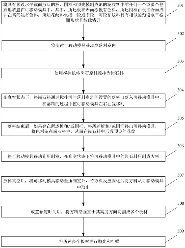
[0135] Now referring to image 3 In another aspect of the present invention further provides a method of producing a controlled pattern in accordance with granite embodiment of the first class of embodiments of the present invention. Each step of the process according to the corresponding operation corresponding to the granite pattern producing apparatus controllable first class of embodiments of the present invention, therefore, is omitted in the following description of some details of the process may be obtained as described above with reference to a more detailed understanding of the method.
[0136] like image 3 As shown, the method comprising the steps of:
[0137] In step 301, having a predetermined cross-sectional shape of the horizontal plate, any one or more of the surround and pre-molded tread compound disposed vertically movable in a mold, wherein the surface is coated plate there colorant, surround the enclosure formed by the plate combined with a colorant and injection therebetween, the pattern material comprises one or more segments, each segment having a similar pattern material horizontal sectional shape and a predetermined offset from each other;
[0138] In step 302, the movable die is moved to the blanking chamber;
[0139] At step 303, the blender raw material is stirred as a granite using a mixer;
[0140] At step 304, in a vacuum state, the granter is collected into the movable mold through the blanket and the falling edge provided between the mixer and the falling chambers, and the movable mold is reciprocated in the process of the falling material;
[0141] At step 305, after the falling material is completed, if there is a plate and / or a frame, the plate and / or the frame remove the movable mold, and the color is stored in the granules, thereby forming a preset in the granite. Pattern;
[0142] At step 306, moving the movable mold is moved to the pressing chamber, and the granular material in the movable mold is pressed into a square material in a vacuum state;
[0143] At step 307, after the vacuum is removed, the movable mold is moved to the pressing outdoor, and the feed is taken out from the movable mold after the reactive reactivity is cured;
[0144] At step 308, after the predetermined time is placed, the feed is cut into a plurality of sheets perpendicular to its height;
[0145] At step 309, the plurality of sheets are polished and waxed.
[0146] The above-mentioned reference is described above with reference to the drawings, which should be noted that the above description and illustrated are illustrative, not the limitation of the invention. In other embodiments of the invention, the method can have more, less or different steps, and the order between the steps, including, and functions, can be different from the description and illustration. For example, usually one step can be divided into multiple sub-steps; multiple steps can be merged into a bigger step, and so on. For example, in addition to the steps described above, the method can also include other conventional process steps in the production of grantrios in the art, such as the process steps mentioned in the context of the present specification. All of these variations are within the spirit and scope of the invention.
[0147] The granite production apparatus and method of the controllable pattern according to the first type of embodiment of the present invention overcomes the conventional method to make a variety of presets, and can make a variety of presets of the shortcomings of random, disorder, shorter, floral pattern. The shape, the shape of the pattern, the shape, thickness, and the length can be pre-set and unrestricted; and because the pattern is regular, the pattern having special effects can be obtained by pair of two sheets. Further, since the pattern is formed in the mold instead of being formed in the mixer, the production efficiency and quality can be improved compared to the original method.
[0148] Second types example
[0149] Now referring to Figure 4 It shows a schematic diagram of a granite production apparatus according to a second type of embodiment of the present invention.
[0150] like Figure 4 As shown in the present invention, the granite production device 400 of the controlled pattern according to the second type of embodiment of the present invention includes:
[0151] The mixer 110 is used to stir at least one of the stone raw materials and the sub-materials, the color paste, the three strokes.
[0152] The falling chamber 120 is located below the agitator 110, and is provided with a blasting port 121 between the mixer 110;
[0153] The movable mold 130 can be entered into the falling chamber 120 such that the agitation of the stone material is capable of falling into the movable mold 130 along the blanket 121;
[0154] The pressing chamber 140 is located on one side of the falling chamber 120 and is connected to the falling chamber 120 comprising a pressing apparatus for pressing the stone material in the movable mold 130 into a square material, wherein the falling housing room 120 and a press chamber 140 can be closed and vacuum, so that the falling and pressing operation is carried out in vacuo;
[0155] The cutting device 150 is configured to cut a material taken out of the movable mold 130 into a plurality of sheets;
[0156] Polishing and waxing device 160 for polishing and waxing the sheets;
[0157] The funnel 410 is located below the falling section 121 in the falling chamber 120, which is the long rectangle of the lower mouth, and the long side of the lower mouth is perpendicular to the long side of the movable mold 130, so that the granarium falling by the falling body is from the funnel The lower mouth falls into the movable mold 130;
[0158] Multiple rope 411, one end of which is fixed on both sides of the funnel 410;
[0159] The lifting device 412 fixed to the top of the falling chamber 120, and the lifting device 412 on both sides of the falling port 121 is connected to the other end of the plurality of rope 411 for boosting the funnel 410 by the at least two rope 411. The distance between the funnel 410 and the material surface is maintained during the falling process.
[0160] In some embodiments, one end of the plurality of rope 411 is fixed on both sides of the funnel 410 and both sides, and in which
[0161] The lifting device 412 is configured to lift the upper port and the lower mouth of the funnel 410, so that when the movable mold 130 reciprocates up to one end of the funnel 410 near the movable mold 130, the lower mouth of the funnel 410 is also close to movable This end of the mold 130.
[0162] Two lifting devices 412 are mounted around the falling port 121, the lifting device 412, for example, a boost motor, and a plurality of rope 411 connected, for example, a wire rope, and a rope is hung down a funnel 410. Wire rope can be, for example, 4 or more.
[0163] Figure 4 The top of the upper right is a top view of the funnel 410. As shown in the figure, the funnel 410 is narrow, and the upper mouth and the lower port are all rectangular. The size of the funnel 410 is, for example, a length of 1.7 meters long, 1.2, a length of 1.7 meters long, 0.25 meters wide, and the funnel itself is 0.6 meters. For example, in the upper mouth of the funnel 410, a four-pointed ear is made, and two liftingers are made on the width side of the funnel, each lifting can be hung by a wire rope, which is lifted by the lift motor.
[0164] The mixer 410 can stir the pattern according to the existing process, that is, the main stirrer is stirred, the silicon, the sub-mixer is stirred with different colors, or spray the color paste of different colors, the toner of different colors (three are three independent) Methods, it can be used singly or in combination), and then the subjungeon passes through the belt into the main mixer, and the stirring is stirred. Unlike existing processes, there are more resins, such as more than 3-5%, which makes the fluidity of the material, and then vacuum-filled. It turned out that it will directly fall into the mold 130 after the blanket 121 constraint, and now fall into the funnel 410. Operate the boost motor so that the funnel 410 is maintained at a distance of 20 to 30 cm from the material surface. At this time, the trolley still carries the mold 130 to reciprocate around the long axis, and the long side of the funnel 410 and the long side of the mold are perpendicular to the horizontal direction. As the surface of the material is increased, the funnel 410 is also lifted, and the distance of the heel surface is maintained. When the funnel 410 is adjacent, when the width side of the mold 130 is in contact with the mold 130, the pulling funnel 410 is adjacent by the hoisting motor, and the traction funnel 410 is adjacent, in contact with the same side of the mold 130 wide side. When the car is running in the other direction, the previously trailed boiling motor allows the wire rope to flush, and the wire rope on the other side slowly tightened, adjusting the frequency converter to match the speed, so that the funnel 410 is the same as the upper mouth and the lower mouth At the same time, it is close to the width side of the same side mold 130. In this way, the lower port of the funnel 410 can be sufficiently close to the wide side of the mold 130 to avoid sufficient falling material at both sides of the mold, thereby increasing the intersection of the end pattern. After the material in the mixer 110 is formed, the material of the treatment of the hopper 410 is similar, and the funnel 410 is lifted onto the mold 130. The mold 130 is carried to the press molding of the pressing chamber 140 by a small vehicle, and then cured, demolded. After waiting for a week, the wool is cut up in the long axis and wide axis, and the wool is cut perpendicular to the wide axis; or, like the existing process, flip to the long axis and the height axis cross-faced surface, perpendicular to the height axis Woolboard. Then, the polishing is the finished plate, that is, the long-length long pattern or ribbed, the pattern and the long side of the plate are substantially parallel.
[0165] Different from the existing process, the stone is randomly dropped, and now the stone is dropped into the funnel 410. It will flow out from the bottom of the weight, and the pattern is forced to stretch and tile in one direction. Parallel texture. If the drain is not uniform, it will be pressed as "mountain pattern". Controlling the density of the pattern can get parallel dense floral or sparse long pattern. That is, by stirring the color different from the mixer (or spraying or flour), the pattern is coherent from the "funnel" from the "funnel" during the falling process, thereby forming a long and coherent Pattern. Thus, by controlling the ratio of the material and the sub-material, the spray, the spray, the pattern can be controlled, and the thickness and distribution density of the pattern can be controlled by controlling the time length of the main stirrer stirring the pattern, and can control the thickness of the pattern, and the speed of the trains With the air floor speed, it can be controlled not to open, thereby achieving the coherence of the pattern, and can also control the density of the pattern to a certain extent.
[0166] The funnel 410 can be applied to the sheet before use before being cured, and the material remains on the funnel 410.
[0167] The above-mentioned reference to the accompanying drawings, the granite production apparatus 400 according to the second type of embodiment of the present invention, which should be noted, and the above description and illustrate are merely examples, not the limitation of the invention. In other embodiments of the invention, the apparatus can have more, less or different components, and the relationship between the connections, including and functions of each component can be different from the described and illustrated. For example, usually one component may include other sub-components in addition to the sub-parts shown and described, and multiple components can be combined into a larger component, and the like. For example, in addition to the components described above and illustrated, the apparatus can also include other conventional components used in the production known to those skilled in the art, such as the components mentioned in the context of the present specification. For example, the mixer 110 can include a main stirrer and a plurality of subdixers, and may also include a slurry and a sprinkle device. All of these variations are within the spirit and scope of the invention.
[0168] Now referring to Figure 5 In another aspect of the invention, a granter production method of a controlled pattern according to a second type of embodiment of the present invention is also proposed. The respective steps of the method correspond to the corresponding operation of the granite production apparatus according to the second type of embodiment of the present invention, and therefore, some details are omitted in the description of the method, and the description is obtained. More detailed understanding of this method.
[0169] like Figure 5 As shown, the granular production method of the controlled pattern according to the second type of embodiment of the present invention includes the following steps:
[0170] At step 501, moving the movable mold is moved to the falling chamber;
[0171] At step 502, at least one of the stone raw materials and the subjigmatism, the color paste, and the chrome, and the color paste, and the color paste is used.
[0172] At step 503, in a vacuum state, the stone material is set to the foil opening between the mixer and the falling chamber and the funnel provided under the blanket, and the holbar is in a narrow rectangle. The long side of the lower mouth is perpendicular to the long side of the movable mold, and the movable mold is reciprocated in the process of the blanket, and the distance of the funnel is adjacent to the material surface;
[0173] At step 504, after the falling material is completed, the movable mold is moved to the pressing chamber, and the graft material in the movable mold is pressed into a square.
[0174] At step 505, after the vacuum is removed, the movable mold is moved to the pressing outdoor, and the feed is removed from the movable mold after the reactive react is cured.
[0175] After step 506, placing a predetermined time, the square cut into a plurality of sheets in a vertical direction of the width or height thereof;
[0176] In step 507, the plurality of polishing sheets and waxing.
[0177] Described above with reference to the drawings according to the production method of controllably granite pattern of a second class of embodiments of the present invention, it should be noted that the above description and drawings are merely exemplary, and not limiting of the present invention. In other embodiments of the present invention, the method may have more, fewer, or different steps, and the relationship between the order of the steps, functions and the like can contain different to that described and illustrated. For example, a step may be generally divided into a plurality of sub-steps; a plurality of steps may be combined into a larger step, and the like. For example, in addition to the above-described steps, the method may further comprise additional conventional process steps known to those skilled in the granite production, processing steps e.g. background section of this specification mentioned. All such variations are within the spirit and scope of the invention.
[0178] Image 6 Shows an example of the use produced according to the production apparatus and method for controllably granite pattern of the second class of embodiments of the present invention granite pattern.
[0179] The apparatus and method for producing granite controllable pattern of a second class of embodiments of the present invention is obtained by blanking manner from falling through the funnel to flow out, to overcome the conventional method can only make a random, disordered, relatively short, disadvantage of the surface pattern, the whole body can be made long lines or mountain lines, and the thickness and density of the pattern can be adjusted; and since the pattern regularity, by two plate halves can be obtained with a pattern of special effects. Further, since the pattern is formed in a mold, instead of being formed in a mixer, compared with the original method can save a lot of time, improves productivity and quality.
[0180] Third type embodiment
[0181] Now referring to Figure 7 Which shows a schematic diagram granite production apparatus according to an embodiment of the third class of embodiments of the present invention is controllable pattern.
[0182] like Figure 7 As shown, granite pattern production means controllable third class of embodiments of the present invention 700 comprising:
[0183] The mixer 110 is used to stir the stone raw material as a granite;
[0184] Blanking chamber 120, located below the stirrer 110 is provided with a blanking opening between it and the mixer;
[0185] Movable mold 130, which is capable of entering the blanking chamber 120, so that a good stirring stone post 121 can be movable mold 130 falls off along the discharge port;
[0186] Compression chamber 140, 120 is located in a side chamber blanking and blanking chamber 120 is connected, which comprises pressing means for pressing the post stone mold 130 to the movable side material, wherein said blanking chamber 120 and pressing chamber 140 can be closed and evacuated together, so that the blanking and pressing operations performed in a vacuum;
[0187] Cutting means 150 ( Figure 7 Not shown), a plurality of square cut sheet material by moving the removable mold 130;
[0188] Polishing and waxing device 160 ( Figure 7 Not shown), for waxing and polishing plate; and
[0189] Spraying means 711, 712 and the sub-dusting apparatus of any one of the mixer 713 or more, wherein,
[0190] The ink-jet device 711 for the movable mold 130 has fallen into the surface layer of the post injection stone paste;
[0191] The dusting layer 712 for post stone surface in the movable mold 130 has fallen into the toner dusting;
[0192] The sub-mixer 713 for sub-130 Naka movable mold material.
[0193] In some embodiments, the production apparatus 700 further granite comprising: a scrap machine 714, for which the post from the stone chamber 110 comminuted blanking movable mold 130 falls. Gang stone from the mixer 110 are of different sizes, the use of scrap 714 may be broken into the same size, and with dusting, spraying and the like, can be obtained some special patterns. The scrap 714 may cause hillock stone forcibly through the mesh, broke into smaller billets. Then, the sub-feed spray or dusting the pieces spaced apart pattern may be finely divided form.
[0194] The ink-jet device 711, device 712 and the sub-dusting mixer 713 can be similar to the corresponding prior art device, the conventional process except that the spraying apparatus 711 of the present invention, dusting device 712 and the secondary mixers 713 is in the blanking operation chamber 120, 130 directly in a mold spraying, dusting off, and the sub-material, rather than the operating within the main mixer 110.
[0195] For example, below the main mixer 110 may increase the port blanking spraying head 4 (blanking respective left and right door 2), is connected behind the spray head pneumatic switch, the pneumatic switch points plastic hose 4 is connected, plastic hose connection blanking the conical funnel outside, a conical funnel 50 cm diameter, 80 cm high, with the fast downward hose connection points of the joints 4, above the sealing, welding only a 1 inch in communication with the outside of the switch, the switch is opened, can be inverted funnel provisioning the color paste (paste may be titanium dioxide, iron oxide pigments, etc. are added to the resin slurry is milled to a respective, desired color when formulated with different ratios), then the isolated switch off in vacuo.
[0196] Main mixer 110 according to the usual process material was stirred, evacuated. When blanking control how much feed falls inside the mold 130 and distributed as appropriate to close off the discharge port, blanking pause, start pneumatic switch, shotcrete spray head, by controlling the spray pattern and the length of the range decision distribution, and then close the spray continues blanking. Repeat until blanking is completed.
[0197] Then, a small vehicle 130 to the pressing mold pressing chamber 140, a vacuum release, mold release, to the longitudinal axis and intersecting the wide faces, with a cutting width perpendicular to the axis wool board, or turned 90 degrees to the major axis and the axial height on the height of the cut perpendicular to the axis wool board, and the polishing is finished board.
[0198] This plate method were as expected after spraying does not move, it may be a long and consistent "mountain pattern", and may be intermittent or varying lengths of cracks agglomerate grain.
[0199] For another example, it is also next to the main mixer 110 to make a next sub-mixer 713, the sub-master mixer 110 and the mixer 713 are connected in the same chamber 120 above the blanking. There may also be other four sub-mixer, respectively leading to a belt agitator 110 and the sub-master mixer 713 next can be fed to the main mixer 110 down depending on the desired effect, a stirrer 713 to stir the sub-pattern, then the next step down material. Blanking during evacuation, the main mixer 110 falls to some extent closed door blanking, mixer 713 sub-blanking. Flow control sub-mixer 713 may be controlled in the sub-pattern material thickness, the control sub-mixer 713 may control blanking distribution pattern distribution. Ingredients sub-mixer 110 and the main material of the sub-mixer 713 are sand with calcium carbonate, calcium carbonate, unsaturated resin, accelerators, curing agent stir the material, but of different colors, in order to thus form a visible pattern. Sub-mixer is closed off to some extent fed blanking door, switched to the primary mixer blanking (blanking stirring main control pattern shape), and so forth until the finish blanking. Typically, multi Ingredients and stiffer, not easy to form a shape after deformation, after a portion of the suspension Ingredients blanking blanking off the main ingredient may be flat, or may be a multi-side side less, may be mountains as downs. Then the sub-material falls onto the main ingredient, the sub-material is quite soft, after dropping to close Ingredients Ingredients stream into substantially the shape of the secondary material may not cover all the main ingredient, so where the sub-material falls, where only pattern, the sub-feed control distribution pattern.
[0200] You can also spray and / or dusting. Vice materials drop, spraying, dusting independent methods may be used alone, may be used together.
[0201] Spraying, spreading the resulting fine powder patterns, the sub-sub agitator off coarse frit pattern can be formed. Preferably, the sub-feed to add some Ingredients (Ingredients with or closest color material) was stirred, and then alternately blanking Ingredients avoid dull pattern out. The main ingredient and sub materials different distributions blanking, pattern different density, a different shape. There is a separate sub-materials, plus a spray, after several sub-feed mix blanking.
[0202] The spraying, dusting, sub feedstock may drop and fall alternately main ingredient, i.e., the sub bulk material falls after a few Ingredients dusting or spraying in a mold so that the pattern formation is large. Alternatively, the spraying, dusting, sub feedstock may drop off with the main ingredient at the same time, so that the pattern is formed more scattered and fragmentary.
[0203] Described above with reference to the accompanying drawings in accordance with a third controllable pattern class of embodiments of the present invention granite production apparatus 700, it should be noted that the above description and drawings are merely exemplary, and not limiting of the present invention. In other embodiments of the present invention, the apparatus may have more, fewer, or different components, and connected to, and functions comprising relationships between the parts can be different from the described and illustrated. For example, typically comprises a component in addition to the illustrated and described sub-components, but may also include other sub-components; a plurality of components may be combined into a larger component, and the like. For example, in addition to the components described above and illustrated, the apparatus may further comprise other components conventionally used in the production of granite apparent to those skilled in, e.g. background section of this specification member mentioned. For example, the master mixer 110 may comprise a plurality of sub-mixers and blenders. All such variations are within the spirit and scope of the invention.
[0204] Now referring to Figure 8 In another aspect of the present invention further provides a method of producing a controlled pattern in accordance with granite embodiment of the third class of embodiments of the present invention. Each step of the process operation corresponding to the respective controllable granite pattern generation apparatus of the embodiment 700 in accordance with a third embodiment of the present invention is based, therefore, some details are omitted in the following description of this method may be described with reference to the above the method of obtaining a more detailed understanding.
[0205] like Figure 8 , According to the present invention, the third type method for producing a controlled pattern of granite embodiment comprises the steps of:
[0206] In step 801, the movable die is moved to the blanking chamber;
[0207] In step 802, using a stirrer to stir the raw material for the post granite stone;
[0208] In step 803, in a vacuum state, the post stones fall through the blanking opening is provided between the movable die and the blanking mixer chamber, movable blanking process, to reciprocate the left and right mold;
[0209] After step 804, the stone falls within a predetermined number and distribution of the posts of the movable mold simultaneously, and a predetermined number of sub-distribution materials, paste, spray toner or at least one stone or post fall on repeated The above process is completed until the blanking;
[0210] In step 805, the movable die is moved to the pressing chamber, the post will be pressed stone prescription movable mold material in a vacuum state;
[0211] In step 806, when it is deflated in vacuo, the movable mold is moved to press outside, to be expected side reaction material after curing taken out from the movable side mold;
[0212] After step 807, placing a predetermined time, the square cut into a plurality of sheets in a vertical direction of the width or height thereof;
[0213] In step 808, the plurality of polishing sheets and waxing.
[0214] In some embodiments, the granite production method of the controllable pattern also includes the step of using a crusher to break the granules prior to the post-moving mold in the granite.
[0215] The above-mentioned reference is described above with reference to the drawings, which should be noted that the above description and illustrated are illustrative, not the limitation of the invention. In other embodiments of the invention, the method can have more, less or different steps, and the order between the steps, including, and functions, can be different from the description and illustration. For example, usually one step can be divided into multiple sub-steps; multiple steps can be merged into a bigger step, and so on. For example, in addition to the steps described above, the method can also include other conventional process steps in the production of grantrios in the art, such as the process steps mentioned in the context of the present specification. All of these variations are within the spirit and scope of the invention.
[0216] Figure 9 An example of a granular pattern produced by a granted pattern using a graded stone production apparatus and a method of controllable pattern according to the third type of embodiment according to the present invention, wherein the left side is shown, which is formed by a pellet shape. Tattoo, the right side illustrated is a clearer group with a larger border of the spray and flour.
[0217] The granite production apparatus and method according to the third type of embodiment according to the present invention are directly dropped into the mold or the slurry, and the flour to the mold is flour, and the mold is slurried, and the laying is laminated. The traditional approach can only make the shortcomings of random, disorder, shorter, surface pattern, you can get a classified, common method, such as special patterns such as agglomerate patterns, before you can only do it before The grain plate can also be used as a long pattern, not formulated, and the pattern, distribution, thickness and density can be conveniently adjusted; and because the pattern has regularity, it can be obtained with special effects through two sheets of plate. picture of. Further, since the pattern is formed in the mold, it is possible to save a lot of time in the mixer, and improve productivity and quality.
[0218] The above-mentioned reference is described above with reference to the accompanying drawings, which is known from the above description, and the common technical features of various embodiments of the present invention are to form a pattern directly in the mold. Instead of forming a pattern in the mixer as in the prior art. Therefore, such as Figure 10 As shown in another aspect of the invention, a granite production method of controllable pattern includes the following steps:
[0219] At step 101, moving the movable mold is moved to the falling chamber;
[0220] At step 102, the blender raw material is stirred as a granite using a mixer;
[0221] At step 103, in a vacuum state, the granter is collected into the movable mold through the blanket and the falling edge provided between the mixer and the falling chamber, and the movable mold is reciprocally movable during the falling process;
[0222] At step 104, a pattern is formed directly in the stone material in the mold while falling.
[0223] At step 105, moving the movable mold is moved to the pressing chamber, pressed into a square material in a vacuum state;
[0224] At step 106, after the vacuum is removed, the movable mold is moved to the pressing outdoor, and the feed is removed from the movable mold after the reactance is cured.
[0225] At step 107, after the predetermined time is placed, the reference is cut into a plurality of sheets perpendicular to its width or height;
[0226] At step 108, the plurality of sheets are polished and waxed.
[0227] The specific details of each step of the method may be referred to the foregoing description, and details are not described herein.
[0228] While the invention has been disclosed by examples, the present invention is not limited thereto. Those skilled in the art will not depart from the various fractures and modifications of the present invention, and the scope of the invention will be included in the scope of the present invention, and the scope of the invention is limited only by the language and equivalent language thereof. The range is accurate.

PUM

no PUM

Description & Claims & Application Information

We can also present the details of the Description, Claims and Application information to help users get a comprehensive understanding of the technical details of the patent, such as background art, summary of invention, brief description of drawings, description of embodiments, and other original content. On the other hand, users can also determine the specific scope of protection of the technology through the list of claims; as well as understand the changes in the life cycle of the technology with the presentation of the patent timeline. Login to view more.

Similar technology patents

Classification and recommendation of technical efficacy words

  • Shorten the time
  • Improve productivity and quality

People also interested in

Why Eureka
Try Eureka