A wire drawing furnace for heating and melting glass base material for optical fiber

A technology of heating furnace and wire drawing furnace, which is applied in glass fiber drawing devices, glass manufacturing equipment, manufacturing tools, etc. It can solve the problems of shaking optical fibers, oxidation of furnace core tubes, and affecting the drawing effect of optical fibers, so as to avoid oxidation and ensure drawing effect , to speed up the effect of air flow

Active Publication Date: 2021-11-16
南通安广美术图案设计有限公司
View PDF7 Cites 0 Cited by
  • Summary
  • Abstract
  • Description
  • Claims
  • Application Information

AI Technical Summary

Problems solved by technology

[0004] The purpose of the present invention is to solve the following shortcomings in the prior art. The upper and lower openings of the wire drawing furnace are open, and the inert gas introduced in order to avoid oxidation caused by air during the wire drawing process will be transferred to the outside of the wire drawing furnace during the heating process, resulting in The air enters the wire drawing furnace, and at the same time, it cannot guarantee whether the air inside the furnace core tube is effectively discharged. This will not only cause the oxidation of the furnace core tube, but also shake the optical fiber, which will affect the drawing effect of the optical fiber. Heating and melting wire drawing furnace

Method used


Image

  • A wire drawing furnace for heating and melting glass base material for optical fiber
  • A wire drawing furnace for heating and melting glass base material for optical fiber
  • A wire drawing furnace for heating and melting glass base material for optical fiber

Examples


Embodiment Construction

[0026] The following will clearly and completely describe the technical solutions in the embodiments of the present invention with reference to the accompanying drawings in the embodiments of the present invention. Obviously, the described embodiments are only some, not all, embodiments of the present invention.

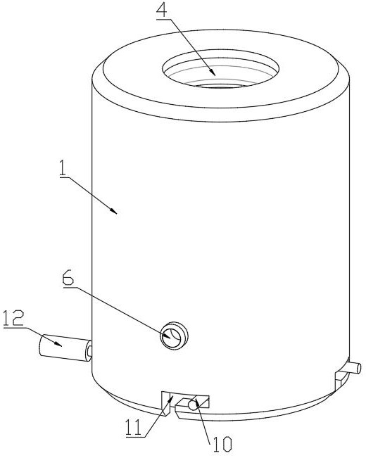
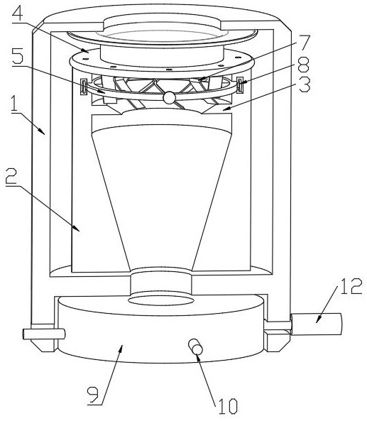
[0027] refer to Figure 1-5 , a drawing furnace for heating and melting optical fiber with glass base material, comprising:

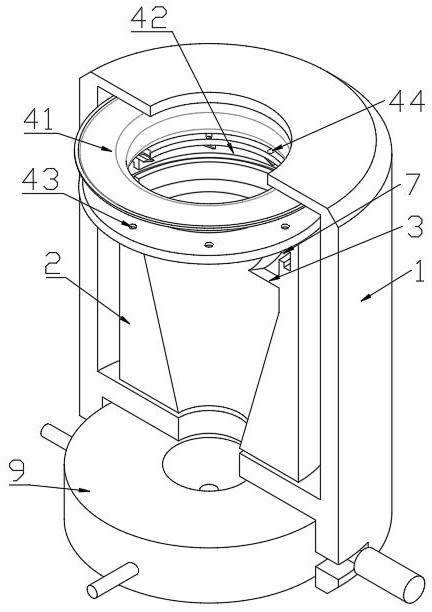
[0028] Furnace body structure, the furnace body structure includes an outer furnace 1 and a heating furnace core tube 2, the heating furnace core tube 2 is installed inside the outer furnace 1, and there is an air inlet cavity between the outer furnace 1 and the heating furnace core tube 2, and the heating furnace core The tube 2 is used to heat and melt the glass base material, and the inner upper end of the heating furnace core tube 2 is fixedly connected with a heat insulating ring 3;

[0029] Sealing gas guiding mechanism 4, sealing gas g...


PUM


Abstract

The invention discloses a wire drawing furnace for heating and melting a glass base material for an optical fiber. The inner upper end of the heating furnace core tube is connected with a heat insulating ring; the sealed gas guiding mechanism includes an elastic ring cover and a retaining ring, and there is a distance between the top of the heating furnace core tube and the outer furnace top wall, so One side of the elastic ring cover is fixedly connected to the top wall of the outer furnace, the retaining ring is connected to the top of the heating furnace core tube, and the elastic ring cover is clamped between the retaining ring and the top of the outer furnace, and the bottom of the elastic ring cover is clamped with a An air outlet; a rotating exhaust assembly installed between the heating furnace core tube and the retaining ring. The invention seals the upper opening during the introduction of the inert gas, avoiding the entry of external air, and at the same time speeds up the discharge of the original gas, ensuring the content of the inert gas and the drawing effect of the optical fiber.

Description

technical field [0001] The invention relates to the technical field of optical fiber drawing, in particular to a drawing furnace for heating and melting a glass base material for an optical fiber. Background technique [0002] In the fiber drawing process, the finished glass tube is fixed, and the bottom end enters the inside of the drawing furnace. The fiber drawing furnace is composed of a furnace core tube for placing the glass base material in the furnace frame. Carbon with high thermal conductivity, such as isotropic graphite, is used for the heater device that heats the furnace core tube, and for the heat insulating material that suppresses the release of heat to the outside. In the process of heating and melting, in order to prevent oxidation of the furnace core tube, rare gases such as argon (Ar), helium (He) or nitrogen (N2) will be fed into the furnace core tube. In addition, inert gas is also fed into the furnace frame to prevent oxidation of heat insulating mate...

Claims


Application Information

Patent Timeline
Patent Type & Authority Patents(China)
IPC IPC(8): C03B37/029
CPCC03B37/029C03B2205/61
Inventor 洪美结
Owner 南通安广美术图案设计有限公司
Why Eureka
Try Eureka